
Method for detecting and correcting clock error lock of CPM signal greater than 1 modulation index

A technique of modulation index and error detection, applied in digital transmission systems, automatic power control, electrical components, etc., can solve problems such as difficult synchronization and high complexity of receivers

Active Publication Date: 2019-09-13
NANJING UNIV OF AERONAUTICS & ASTRONAUTICS
View PDF3 Cites 2 Cited by
  • Summary
  • Abstract
  • Description
  • Claims
  • Application Information

AI Technical Summary

Problems solved by technology

Although the CPM signal has many advantages, the resulting problems are the high complexity of the receiver and the difficulty of synchronization

Method used


Image

  • Method for detecting and correcting clock error lock of CPM signal greater than 1 modulation index
  • Method for detecting and correcting clock error lock of CPM signal greater than 1 modulation index
  • Method for detecting and correcting clock error lock of CPM signal greater than 1 modulation index

Examples


Embodiment Construction

[0041] The present invention is described in further detail now in conjunction with accompanying drawing.

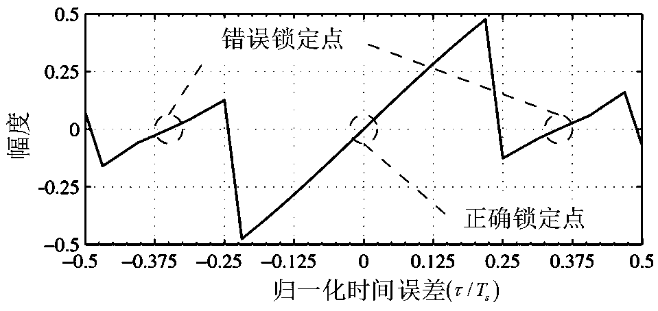
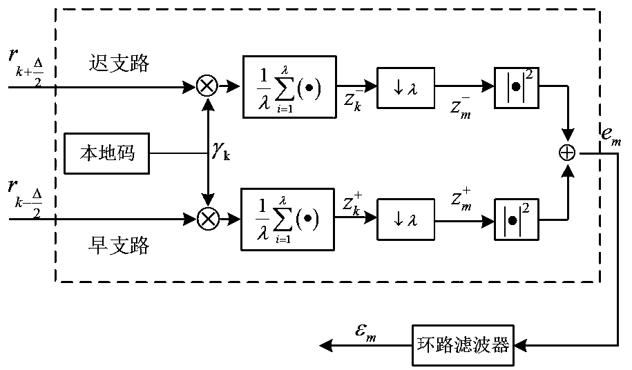
[0042] The method that the present invention proposes to solve the delay-locked loop error lock includes: when the modulation index of the CPM signal is a half-integer greater than 1, the S-curve of the delay-locked loop exists such as figure 1 For the multiple zero-crossing points shown, an error detection decision device is introduced to detect whether the tracking loop is locked incorrectly and correct it. The invention has been verified on the Matlab platform, and it can be seen from the simulation results that when there is no error locking and when there is error locking, different modulation indices have different effects on the working process of the error detection and decision device. figure 2 is the delay locked loop used in the present invention.

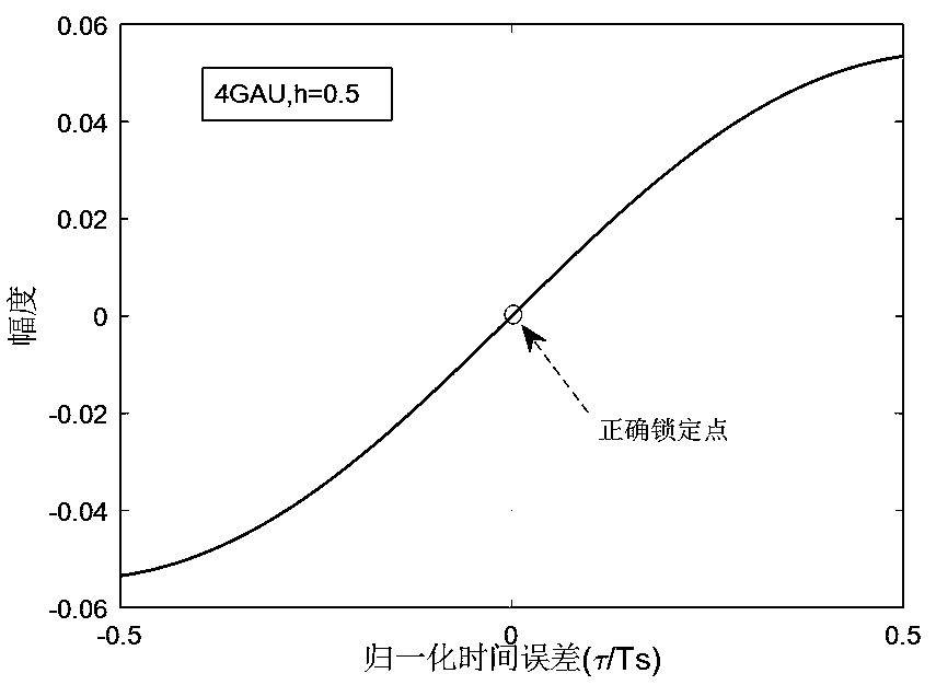
[0043] image 3 , Figure 4 with Figure 5 Respectively represent the S-curves of the delay-locked loop in ...


PUM


Abstract

The invention discloses a method for detecting and correcting a clock error lock of a CPM signal greater than 1 modulation index. When the modulation index of the CPM signal is a half integer greaterthan 1, a signal has a plurality of positive slope zero-crossing points in half of code element time through an S curve of the delay locking ring; mistaken locking of the delay locking ring is caused.An error detection decision device is introduced to detect whether the tracking ring is locked mistakenly. When error lock occurs, the output of an error accumulator in the error detection decision device can exceed a set threshold. A judgment is made that the delay locked loop has error locking. The delay to a correct locking interval is pushed through an error detector and the value of an erroraccumulator is reset to be 0 under the condition of setting an appropriate threshold value, an appropriate weighting coefficient and an appropriate propelling interval, and the tracking loop enters acorrect tracking process. Through verification on a Matlab platform, under the condition of different modulation indexes, the error detection decision device can correctly judge the false lock and enable the delay locking ring to enter a correct locking interval again.

Description

technical field [0001] The invention belongs to the field of digital communication, and specifically relates to solving the wrong locking problem caused when a CPM signal with a modulation index greater than 1 passes through the S-curve of a delay-locked loop and has multiple zero-crossing points with a positive slope within half a symbol. Background technique [0002] Continuous Phase Modulation (CPM) is highly regarded for its bandwidth efficiency and constant RF envelope. This type of modulation signal is especially attractive in radio channels with nonlinear amplifiers because it allows us to fully utilize the amplifier power. Although the CPM signal has many advantages, the resulting problems are the high complexity of the receiver and the difficulty of synchronization. [0003] Synchronization is an important practical issue in both digital communication systems and analog communication systems employing coherent demodulation. Since the receiving and receiving ends a...

Claims


Application Information

Patent Timeline
IPC IPC(8): H04L7/033H03L7/081
CPCH03L7/081H03L2207/14H04L7/033
Inventor 党小宇管寅松
Owner NANJING UNIV OF AERONAUTICS & ASTRONAUTICS
Learn More