Skin inspection lamp with camera shooting system

A technology of a camera system and an inspection lamp, applied in the field of inspection lamps, can solve the problems of inconvenient copying, inconvenient use, inconvenience, etc., and achieve the effect of easy copying of images and convenient use.

CN110236495AInactive Publication Date: 2019-09-17徐州市科诺医学仪器设备有限公司
0 Cites 0 Cited by

Patent Information

Authority / Receiving Office
CN · China
Patent Type
Applications(China)
Current Assignee / Owner
Publication Date
2019-09-17
Estimated Expiration
Not applicable · inactive patent

Smart Images

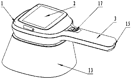
  • Figure 1
    Figure 1
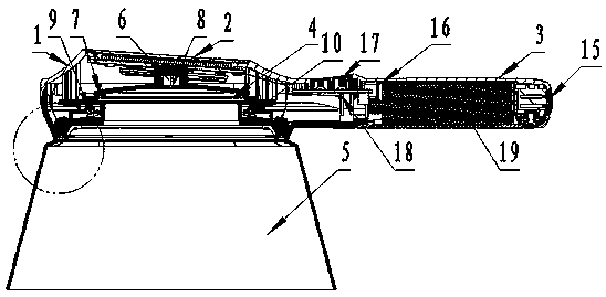
  • Figure 2
    Figure 2
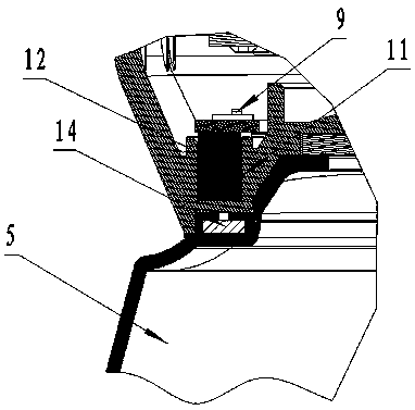
  • Figure 3
    Figure 3
Patent Text Reader

Abstract

The invention relates to a skin inspection lamp with a camera shooting system. A display screen is arranged at the upper part of a housing; a camera is arranged at the lower part of the display screen; a fixing frame is arranged in the housing, and is movably connected with a lens; a hole is formed in the upper part of the fixing frame; the center line of the hole and the center line of the camera are in the same straight line; light sources are uniformly distributed on the periphery of the lens; a translucent plate is arranged at the lower part of the light source; a groove is formed in the lower part of the housing; magnet pieces are uniformly and fixedly arranged in the groove; a magnet ring is embedded in the upper end of a shading hood; the magnet pieces in the groove are mutually attracted with the magnet ring on the shading hood; a handle is arranged at one end of the housing; a charging hole is formed in one end of the handle; a battery groove is formed in the handle; and a key is arranged on the surface of the handle. According to the skin inspection lamp disclosed by the invention, the camera shooting system is combined with the skin inspection lamp, so that functions of observing, shooting and storing are achieved, the problems that a gap is formed between a mobile phone and a magnifying glass, so that the magnifying glass can reflect strong external light rays to form an inverted image and the inverted image is overlapped with the shot images can be avoided, the operator can conveniently use the skin inspection lamp, and image copying is more convenient.
Need to check novelty before this filing date? Find Prior Art

Description

technical field

[0001] The invention relates to an inspection lamp, in particular to a skin inspection lamp with a camera system. Background technique

[0002] The skin examination lamp, also known as the Wood lamp, was invented by the American physicist Wood in 1903. It emits light waves with a wavelength of 320-400nm, and the peak wavelength is at 365nm. The output power of the Wood lamp is low, generally 1mW / cm2. The use of skin examination lights as a diagnostic research tool in dermatology is expanding. It is mainly used to detect abnormal pigmentation diseases, skin infections, abnormal porphyrin metabolism diseases (such as: acne, tinea capitis, tinea versicolor, tinea versicolor, erythrasma, tinea armpit; some pigmented lesions such as chloasma, age spots , coffee spots, etc., as well as neurofibromas, skin tumors). At the same time, the application in chemical peeling can avoid excessive medication, monitor the oral compliance of a certain drug, monitor the effic...

Examples

Embodiment Construction

[0019] The present invention will be described in detail below in conjunction with the accompanying drawings and specific embodiments.

[0020] Such as Figure 1 to Figure 4 As shown, the present invention is an intelligent skin examination lamp, which is composed of a housing 1, a display screen 2, a handle 3, a lens 4 and a light shield 5, the upper part of the housing 1 is provided with a display screen 2, and the display screen The lower part of 2 is provided with camera 6, housing 1 is provided with fixed frame 7, and fixed frame 7 is fixedly connected with lens 4, and fixed frame 7 top is provided with hole 8, and the center line of hole 8 and the center line of camera 6 are on the same straight line A light source 9 is evenly distributed around the lens 4, a light-transmitting plate 10 is arranged on the lower part of the light source 9, a groove 11 is arranged on the lower part of the housing 1, a magnet block 12 is uniformly fixed in the groove 11, and the upper end o...