
Bag clamping conveying mechanism and bag clamping conveying method

A transmission mechanism and bag clamping technology, which is applied in packaging and other directions, can solve the problems of large effective working space of bags, limited coding position, and affecting application functions, etc., and achieve the effect of compact structure, ensuring accuracy, and saving effective space

Pending Publication Date: 2019-09-17
LANGRUI PACKAGING TECH CANGZHOU CO LTD
View PDF0 Cites 3 Cited by
  • Summary
  • Abstract
  • Description
  • Claims
  • Application Information

AI Technical Summary

Problems solved by technology

[0002] In the field of packaging machines, especially in horizontal packaging machines, bags need to be conveyed between each station. Most of the bag transmission mechanisms in existing horizontal packaging machines are fixed and moved by two layers of multiple clips, through different The opening and closing sequence and the movement of the mobile clip are used to realize the bag transmission. Due to the limitation of the structure, this kind of transmission is mostly linear, and the bag can only be transmitted in a straight line for a certain distance. Due to the range of motion and the weight of the clip itself, it cannot reach too high. The transmission speed is high, and the distance between the clips is fixed when working. When it is necessary to change bags of other widths, it is necessary to loosen the bolts, adjust the distance, and then tighten them. The time is long, the efficiency is low, and the device takes up the effective work of the bag. The space is relatively large, which affects the realization of other application functions, such as limited coding positions, etc.

Method used


Image

  • Bag clamping conveying mechanism and bag clamping conveying method
  • Bag clamping conveying mechanism and bag clamping conveying method
  • Bag clamping conveying mechanism and bag clamping conveying method

Examples


Embodiment Construction

[0053] Embodiments of the present invention will be further described in detail below in conjunction with the accompanying drawings and examples. The following examples are used to illustrate the present invention, but should not be used to limit the scope of the present invention.

[0054] In the description of the present invention, unless otherwise stated, the meaning of "plurality" is two or more; the terms "upper", "lower", "left", "right", "inner", "outer" , "front end", "rear end", "head", "tail", etc. indicate the orientation or positional relationship based on the orientation or positional relationship shown in the drawings, and are only for the convenience of describing the present invention and simplifying the description, rather than Nothing indicating or implying that a referenced device or element must have a particular orientation, be constructed, and operate in a particular orientation should therefore not be construed as limiting the invention. In the descrip...


PUM


Abstract

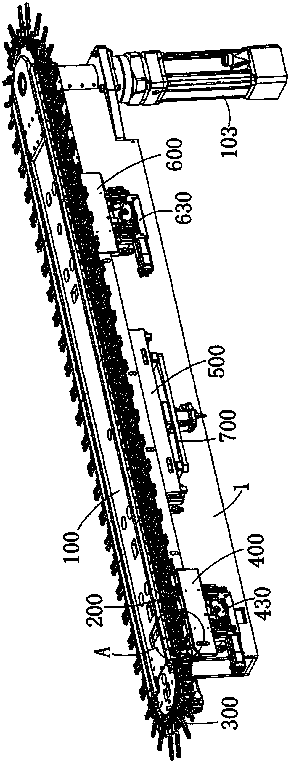
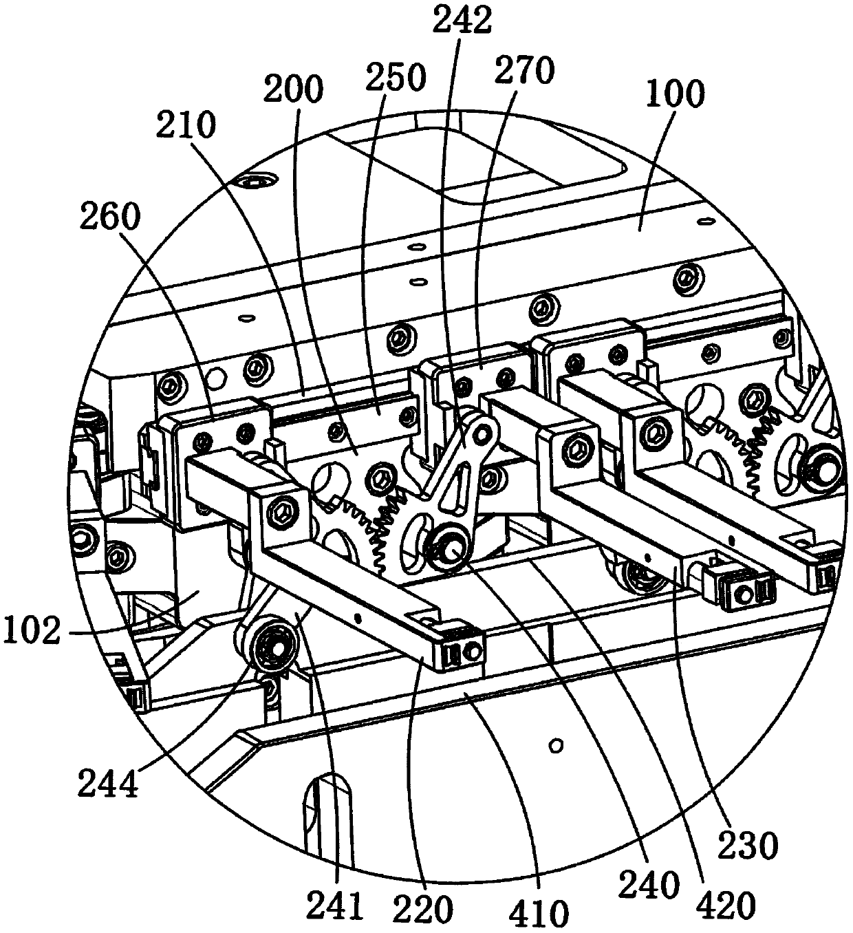
The invention discloses a bag clamping conveying mechanism and a bag clamping conveying method. The bag clamping conveying mechanism comprises a rack, a conveying mechanism and clamping hand assemblies arranged on the conveying mechanism and used for conveying bags, wherein the conveying mechanism comprises a chain wheel, a chain and a chain wheel driving motor used for driving the chain wheel to rotate, the clamping hand assemblies comprise the A-type clamping hand assemblies and the B-type clamping hand assemblies, one or more A-type clamping hand assemblies form a group, one or more B-type clamping hand assemblies form a group, the number of the A-type clamping hand assemblies in each group is the same as the number of the B-type clamping hand assemblies in each group, and with the group as a unit, the A-type clamping hand assemblies and the B-type clamping hand assemblies are arranged at intervals. According to the bag clamping conveying mechanism and the bag clamping conveying method, packaging bags can be continuously and quickly conveyed, so that a packaging machine can achieve a faster working speed, and the working efficiency is greatly improved; and the distance between clamping hands of the hand clamping assemblies is adjusted through the control of a guide rail mechanism, actions such as bag opening and bag closing are completed, and the overall structure is compact.

Description

technical field [0001] The invention relates to the technical field of packaging machinery, in particular to a bag-clamping transmission mechanism and a bag-clamping transmission method. Background technique [0002] In the field of packaging machines, especially in horizontal packaging machines, bags need to be conveyed between each station. Most of the bag transmission mechanisms in existing horizontal packaging machines are fixed and moved by two layers of multiple clips, through different The opening and closing sequence and the movement of the mobile clip are used to realize the bag transmission. Due to the limitation of the structure, this kind of transmission is mostly linear, and the bag can only be transmitted in a straight line for a certain distance. Due to the range of motion and the weight of the clip itself, it cannot reach too high. The transmission speed is high, and the distance between the clips is fixed when working. When it is necessary to change bags of ...

Claims


Application Information

Patent Timeline
Patent Type & Authority Applications(China)
IPC IPC(8): B65B43/16
CPCB65B43/16
Inventor 汪洪静李若愚叶兆亮
Owner LANGRUI PACKAGING TECH CANGZHOU CO LTD
Learn More