Follower fixture for shaft products, and fixture unit thereof

A fixture and product technology, applied in the direction of clamping, manufacturing tools, metal processing machinery parts, etc., can solve the problems of circumferential rotation error, difficulty in realizing circumferential clamping and positioning, and different positioning references, so as to prevent circumferential rotation, Effects of preventing damage and improving efficiency and precision

Active Publication Date: 2019-10-18
CHONGQING UNIV
View PDF10 Cites 1 Cited by
  • Summary
  • Abstract
  • Description
  • Claims
  • Application Information

AI Technical Summary

Problems solved by technology

[0003] Due to the smooth outer peripheral surface of shaft products, it is difficult to achieve circumferential clamping and positioning
The existing clamping bases for shafts generally use arc-shaped grooves or V-shaped grooves to directly support shaft products, but when shaft products are transported between different stations, there will inevitably be circumferential rotation er

Method used


Image

  • Follower fixture for shaft products, and fixture unit thereof
  • Follower fixture for shaft products, and fixture unit thereof
  • Follower fixture for shaft products, and fixture unit thereof

Examples


Example Embodiment

[0045] Example 1

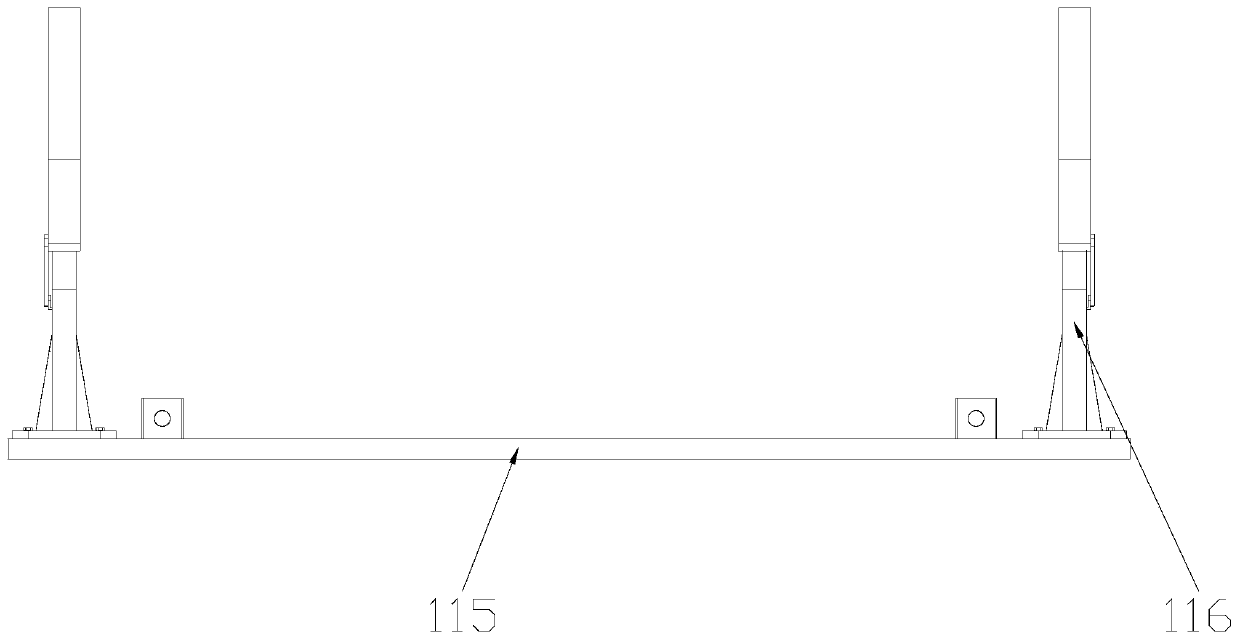
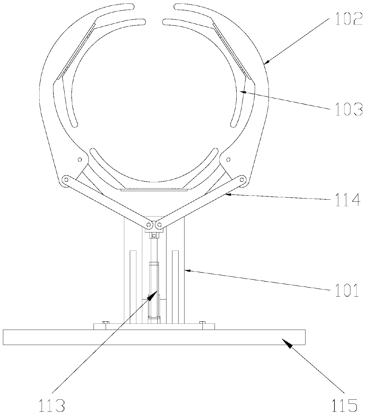
[0046] Such as figure 1 As shown, it is a schematic structural diagram of Embodiment 1 of the traveling clamp for shaft products of the present invention. The traveling clamp for shaft products of this embodiment includes a traveling base 115; the traveling base 115 is provided with at least two clamp units 116 whose axes are located on the same straight line and are used to hold the shaft products.

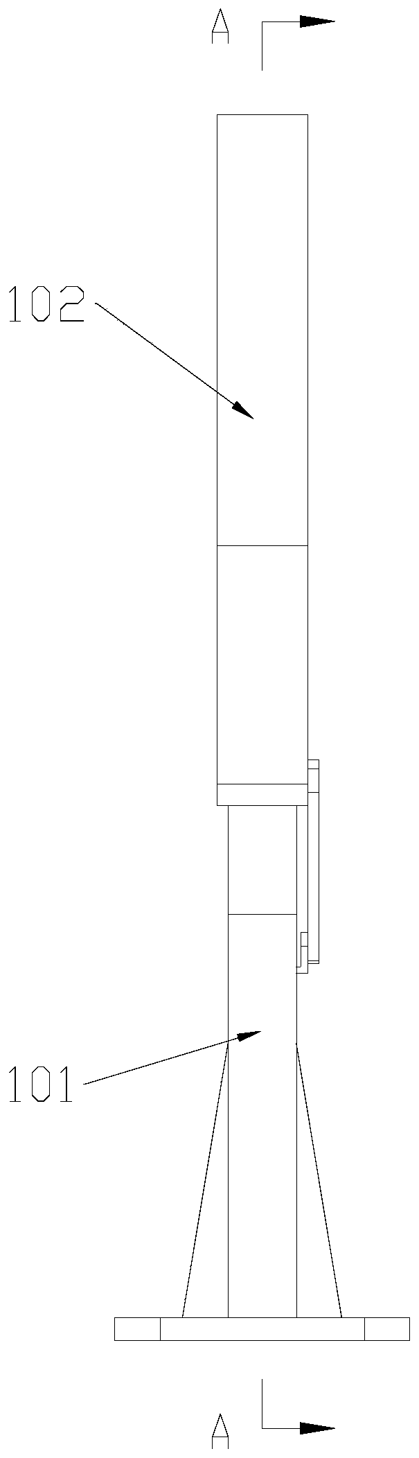
[0047] The clamp unit of this embodiment includes a holding device base 101. Both ends of the holding device base 101 are respectively provided with holding arms 102 that are rotatably matched with the holding device base 101, and the holding device base 101 is provided with a holding arm 102 for driving the holding arms 102 to rotate and hold tightly. A flexible drive mechanism for shaft products or loose shaft products; the holding device base 101 and the holding arm 102 are respectively provided with arc-shaped grooves or V-shaped grooves that match the shaft pro...

Example Embodiment

[0054] Example 2

[0055] This embodiment also proposes a traveling clamp for shaft products, which includes a traveling base 115. At least three clamp units 116 for holding shaft products are spaced apart on the traveling base 115.

[0056] Among all the clamp units 116, the two clamp units 116 located at both ends are end clamp units, and the clamp unit 116 located between the two end clamp units is an intermediate clamp unit. The axes of the two end clamp units are always on the same straight line; among all the middle clamp units, the axis of at least one middle clamp unit and the axes of the two end clamp units are not collinear.

[0057] Specifically, the clamp unit 116 can be installed on the accompanying base 115 in various ways, such as:

[0058] All the clamp units 116 are fixedly installed on the traveling base 115; or,

[0059] The accompany base 115 is provided with a longitudinal slide rail parallel to a straight line, and among all the gripper units 116 whose axis is co...


PUM


Abstract

The invention discloses a fixture unit. The fixture unit comprises a clamp base, wherein clamping arms forming rotary fit with the clamp base are arranged at the two ends of the clamp base separately,and a flexible drive mechanism used for driving the clamping arms to rotate and clamp the shaft products or release the shaft products is arranged on the clamp base; and arc-shaped grooves or V-shaped grooves matched with the shaft products are formed in the clamp base and the clamping arms separately. The invention further discloses a follower fixture for the shaft products. The follower fixturefor the shaft products, and the fixture unit thereof are capable of realizing circumferential clamping fixing for the shaft products, being used for transferring the shaft products among different stations, and increasing the efficiency and accuracy.

Description

Technical field [0001] The invention belongs to the technical field of mechanical tooling and fixtures, and specifically is a traveling clamp for shaft products and a clamp unit thereof, and particularly a traveling clamp suitable for large shaft products. Background technique [0002] The accompanying fixture is a machine tool fixture that automatically moves and transfers the installed workpiece between each station. Accompanying fixtures are mainly used in automatic production lines, machining centers, flexible manufacturing systems, and other automated production for workpieces with irregular shapes and inconvenient automatic positioning, clamping and transportation. After the workpiece is installed and positioned on the accommodating fixture, the accommodating fixture is transported to each station by the conveying device. The accompanying fixture is generally positioned on the machine tool with its bottom plane and two positioning holes, and is clamped by the clamping mech...

Claims


Application Information

Patent Timeline
IPC IPC(8): B23Q3/06B23Q7/00
CPCB23Q3/064B23Q7/00
Inventor 杨波陈嵘华王时龙陈俊明王彦凯杨叶枫
Owner CHONGQING UNIV
Why Eureka
Try Eureka