Repair tool after pit slot detection
A post-inspection and pit-groove technology is applied in the field of road maintenance equipment and post-pot inspection repair tools, which can solve problems such as the influence of the filling effect, the influence of the edge effect, and the influence on the construction efficiency, so as to achieve easy filling work, high construction efficiency, and good cutting effect. Effect
- Summary
- Abstract
- Description
- Claims
- Application Information
AI Technical Summary
Problems solved by technology
Method used
Image
Examples
Embodiment 1
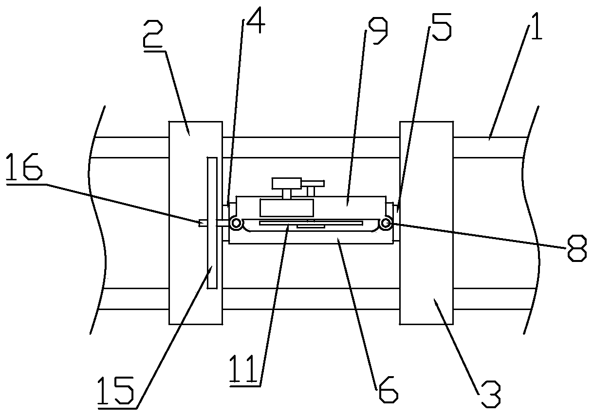
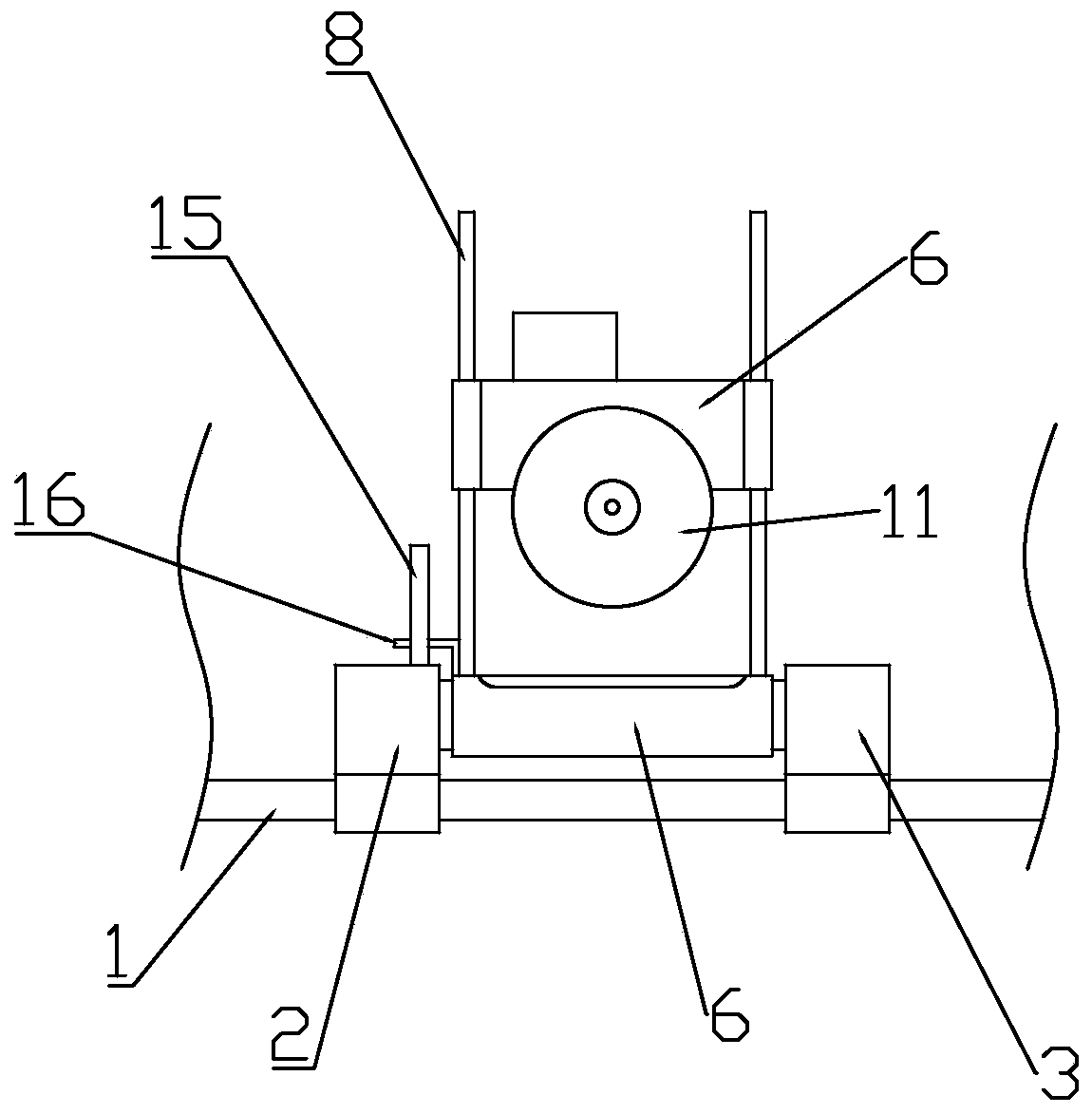
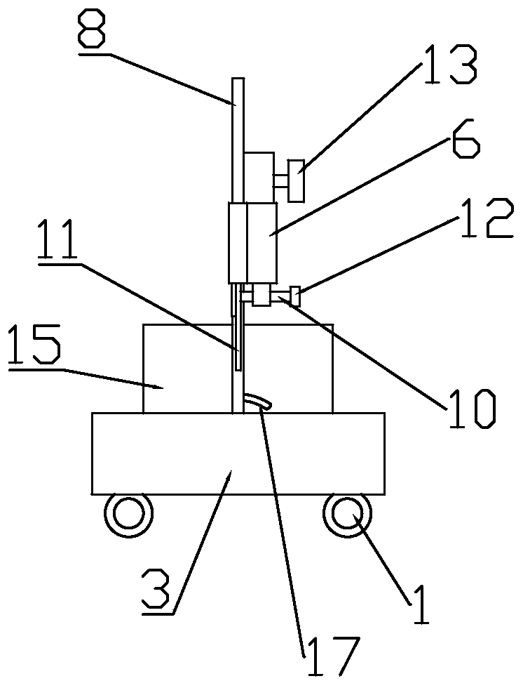
[0030] Such as figure 1 As shown, this embodiment discloses a repairing tool after pothole detection, a repairing tool after pothole detection, including a main vehicle body capable of locking the position, and a machine vision component for measuring the edge of the pothole is provided on the main vehicle body , a material storage assembly for placing fillers, a filling assembly for conveying fillers in the pit, and a leveling assembly (not shown in the accompanying drawings) for leveling and repairing the surface of the pit, the bottom of the main body is set There is a cutting assembly for cutting the edge of the pit groove, and the position of the main vehicle body corresponding to the cutting assembly is opened to facilitate the operation of the operator.
[0031] The cutting assembly includes two first optical axes 1 horizontally arranged on the bottom surface of the main vehicle body. The first optical axis 1 is pierced with a first base 2 and a second base 3 through a ...
Embodiment 2
[0046] refer to Figure 7 , the difference between this embodiment and embodiment 1 is:
[0047] The opposite sides of the first base 2 and the second base 3 are provided with several horizontal buffer springs 20, the horizontal buffer springs 20 are in the same direction as the first optical axis 1; Several vertical buffer springs 21 are provided, and the vertical buffer springs 21 are in the same direction as the second optical axis 8 .
[0048] Compared with Embodiment 1, this embodiment is equipped with buffer springs on the first optical axis and the second optical axis, so that both the edge of the cutting track and the depth of cutting are more controllable during cutting, and in the non-working state , the cutting assembly is located relatively in the middle of the entire assembly to protect the cutting saw blade and prolong its service life.
Embodiment 3
[0050] refer to Figure 8 and Figure 9 , the difference between this embodiment and embodiment 1 is:
[0051] The first base 2 and the second base 3 are also provided with a horizontal lead screw 22 parallel to the first optical axis 1 through the lead screw nut. The vertical leading screw 23, the end of horizontal leading screw 22 and vertical leading screw 23 are respectively connected with the stepper motor 24 that is fixed on the main vehicle body and on the hollow shaft 6.
[0052] Compared with Embodiment 1, this embodiment adds a horizontal lead screw for driving the cutting assembly to move in the x-axis direction in the first base and the second base, and adds a horizontal lead screw for driving the cutting assembly to move in the x-axis direction on the saw blade frame. The vertical lead screw moving in the z-axis direction is controlled by a stepping motor, so that it can be intelligently controlled by a single-chip microcomputer, without manual cutting, which is...
PUM
 Abstract
Description
Claims
Application Information
 - R&D
- Intellectual Property
- Life Sciences
- Materials
- Tech Scout
- Unparalleled Data Quality
- Higher Quality Content
- 60% Fewer Hallucinations
Browse by: Latest US Patents, China's latest patents, Technical Efficacy Thesaurus, Application Domain, Technology Topic, Popular Technical Reports.
© 2025 PatSnap. All rights reserved.Legal|Privacy policy|Modern Slavery Act Transparency Statement|Sitemap|About US| Contact US: help@patsnap.com


