
Integrated flood discharging system for tailing pond flood-sewage diversion and ore pulp conveying

A technology of tailings storage and slurry, which is applied in the field of tailings storage, and can solve problems such as poor separation of engineering floods and sewage, and difficulties in the maintenance of tailings transportation pipelines.

Pending Publication Date: 2019-09-17
SHAANXI METALLURGICAL DESIGN & RES INST CO LTD
View PDF0 Cites 1 Cited by
  • Summary
  • Abstract
  • Description
  • Claims
  • Application Information

AI Technical Summary

Problems solved by technology

[0005] The purpose of the present invention is to provide an integrated flood drainage system for flood and sewage diversion and slurry transportation in tailings ponds, so as to solve the problems of poor flood and sewage diversion and difficult maintenance of tailings transportation pipelines in existing projects

Method used


Image

  • Integrated flood discharging system for tailing pond flood-sewage diversion and ore pulp conveying
  • Integrated flood discharging system for tailing pond flood-sewage diversion and ore pulp conveying
  • Integrated flood discharging system for tailing pond flood-sewage diversion and ore pulp conveying

Examples


Embodiment 1

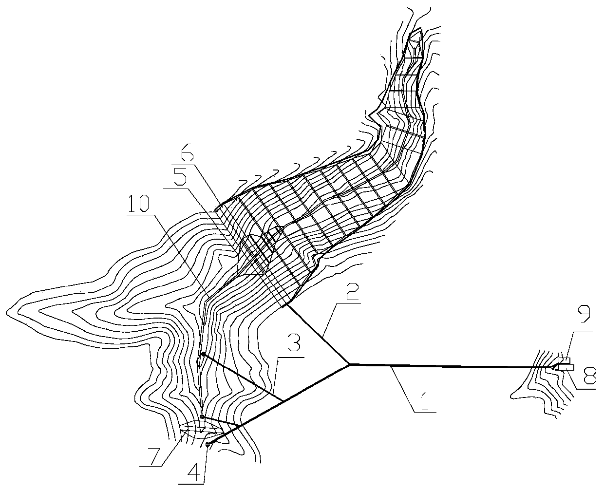
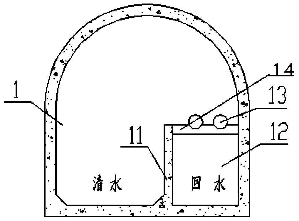
[0024] An integrated flood drainage system for flood and sewage diversion and slurry transportation in tailings ponds, including a main flood drainage tunnel, the upstream side of the main flood drainage tunnel is respectively connected with a flood drainage branch tunnel and a tailings conveying branch tunnel, and the main flood drainage tunnel along the drainage A water partition wall is set along the length of the main flood tunnel, and the water wall and the side wall of the main flood discharge tunnel form a return channel. The return channel is arranged along the length direction of the main flood discharge tunnel and the branch tunnels. A cover plate is set above the inner return channel between the top of the water partition wall and the main flood discharge tunnel, and a tailings conveying pipeline is arranged on the cover plate, and the tailings conveying pipeline is arranged along the length direction of the main flood discharge tunnel and the tailings conveying branc...

Embodiment 2

[0026] On the basis of Embodiment 1, the flood discharge branch tunnel is also communicated with an overflow well.


PUM


Abstract

The invention discloses an integrated flood discharging system for tailing pond flood-sewage diversion and ore pulp conveying and belongs to the technical field of tailing ponds. The integrated flood discharging system aims at solving the problems that flood-sewage diversion of existing engineering is poor, and a tailing conveying pipeline is difficult to repair and maintain. The integrated flood discharging system comprises a flood-discharging main tunnel, the upstream side of the flood-discharging main tunnel communicates with a flood-discharging branch tunnel and a tailing conveying branch tunnel, a cutoff wall is arranged in the flood-discharging main tunnel, a water return canal is defined by the cutoff wall and the side wall of one side of the flood-discharging main tunnel, a cover plate is arranged on the position, in the flood-discharging main tunnel, of the upper part of the water return canal, a tailing conveying pipeline is arranged on the cover plate, a clear water channel is formed by the cutoff wall and the side wall of the other side of the flood-discharging main tunnel, the downstream side of the clear water channel communicates with a force dissipating pool, the downstream side of the water return canal communicates with a water return pool, a flood blocking dam, a tailing initial dam and a tailing accumulation dam are further included, and a seepage discharging blind ditch is arranged between the flood blocking dam and the tailing initial dam and communicates with the clear water channel side of the flood-discharging branch tunnel. The integrated flood discharging system is suitable for tailing pond flood-sewage diversion and ore pulp conveying.

Description

technical field [0001] The invention belongs to the technical field of tailings ponds, and in particular relates to an integrated flood discharge system for flood and sewage diversion and slurry transportation of tailings ponds. Background technique [0002] According to the natural geological conditions of our country, most of the tailings ponds built on the ground exist in valleys. The construction investment of the tailings pond project is mainly concentrated in two parts: the tailings dam body and the flood drainage system. At present, the common forms of flood drainage system are flood dam + chute + culvert flood discharge system and overflow well + tunnel flood discharge system. The purpose of setting up the flood drainage system in the tailings pond is twofold: one is to remove the heavy rain in the pond in time; the other is to recover the clarified water in the pond. In the past few decades, due to the lack of formal design and insufficient environmental protectio...

Claims


Application Information

Patent Timeline
IPC IPC(8): E02B8/06E02B8/00
CPCE02B8/00E02B8/06
Inventor 卢星郑卫琳陈晓博杨超群王仕杰黄晓毅罗小新
Owner SHAANXI METALLURGICAL DESIGN & RES INST CO LTD
Learn More