Energy-saving environment-friendly automobile exhaust structure

A technology for vehicle exhaust, energy saving and environmental protection, which is applied to exhaust devices, mechanical equipment, engine components, etc., and can solve problems such as slow engine temperature rise, weak vehicle power, and slow engine reaching operating temperature.

Active Publication Date: 2019-09-17
佛山日克耐热材料有限公司
View PDF6 Cites 2 Cited by
  • Summary
  • Abstract
  • Description
  • Claims
  • Application Information

AI Technical Summary

Problems solved by technology

[0002] The car water tank is an important part installed on the front side of the car engine. Its main function is to cool the engine through the circulating water inside when the engine is working. However, in the colder winter, especially in the cold north In other regions, when the car is started in a cold state, due to the low temperature, the speed of the engine to reach the operating temperature is relatively slow, which in turn makes the temperature of the engine rise more slowly, resulting in weak power of the car and increased fuel consumption, and the exhaust gas emitted by the car contains high levels of Therefore, it is necessary to design an energy-saving and environment-friendly automobile exhaust structure. When the car is cold-started, the hot exhaust gas is used to heat the water tank, so that the water temperature of the water tank can quickly reach the working temperature, so that the engine can reach the working temperature more quickly. Temperature, thereby improving power performance and saving energy consumption

Method used


Image

  • Energy-saving environment-friendly automobile exhaust structure
  • Energy-saving environment-friendly automobile exhaust structure
  • Energy-saving environment-friendly automobile exhaust structure

Examples


Embodiment Construction

[0020] The following will clearly and completely describe the technical solutions in the embodiments of the present invention with reference to the accompanying drawings in the embodiments of the present invention. Obviously, the described embodiments are only some, not all, embodiments of the present invention.

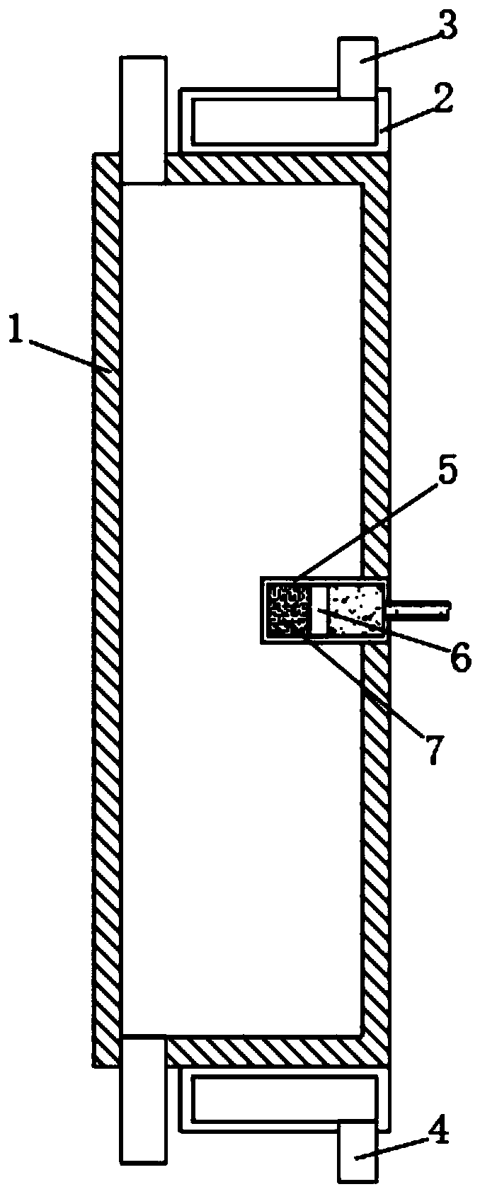
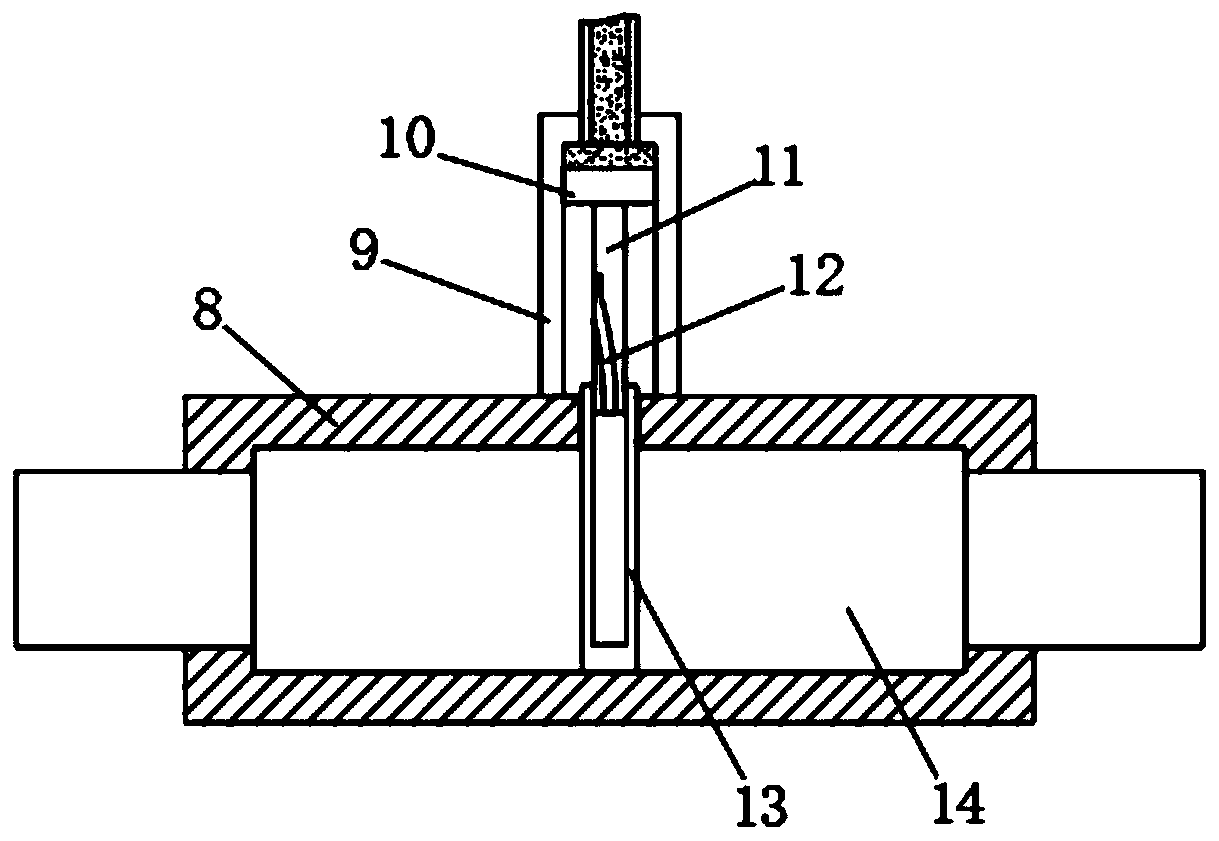
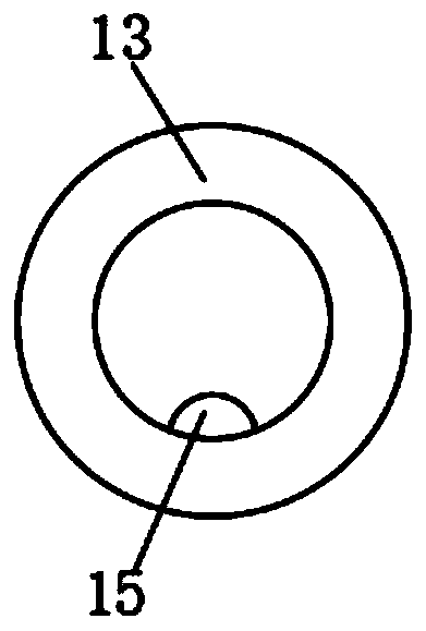
[0021] refer to Figure 1-6 , an energy-saving and environment-friendly automobile exhaust structure, including a flue gas heating box 2 fixedly installed on a water tank 1 and a flue gas circulation control mechanism, and the flue gas circulation control mechanism communicates with the flue gas heating box 2, and the flue gas heating box 2 It is a hollow box structure, and the two sides of the flue gas heating box 2 are respectively connected with the inlet port 4 and the gas outlet port 3. The flue gas circulation control mechanism includes a disc-shaped flue gas circulation box 8 with a hollow structure, and the flue gas circulation box The side wall of 8 is conne...


PUM


Abstract

The invention discloses an energy-saving and environment-friendly automobile exhaust structure. The energy-saving and environment-friendly automobile exhaust structure comprises a smoke heating tank and a smoke circulation control mechanism, wherein the smoke heating tank is fixedly arranged on a water tank; the smoke circulation control mechanism is communicated with the smoke heating tank; the smoke heating tank is of a hollow tank body structure; in addition, an air inlet end and an air outlet end are respectively connected to two sides of the smoke heating tank; the smoke circulation control mechanism comprises a disc-like smoke circulation box with a hollow structure; an air inlet pipe, a first air outlet pipe and a second air outlet pipe are connected to the side wall of the smoke circulation box along the circumferential direction of the smoke circulation box; the air inlet pipe is connected to the exhaust end of an automobile engine; an automobile exhaust pipe is connected with the first air outlet pipe; the second air outlet pipe is connected with the air inlet end. According to the energy-saving and environment-friendly automobile exhaust structure disclosed by the invention, heat-containing waste gases are used for heating the water tank when an automobile is started in a cold state, so that the water temperature of the water tank quickly reaches operating temperature, further the engine can reach the operating temperature more quickly and eventually dynamic performance is improved; in addition, energy consumption is reduced.

Description

technical field [0001] The invention relates to the technical field of automobiles, in particular to an energy-saving and environment-friendly automobile exhaust structure. Background technique [0002] The car water tank is an important part installed on the front side of the car engine. Its main function is to cool the engine through the circulating water inside when the engine is working. However, in the colder winter, especially in the cold north In other regions, when the car is started in a cold state, due to the low temperature, the speed of the engine to reach the operating temperature is relatively slow, which in turn makes the temperature of the engine rise more slowly, resulting in weak power of the car and increased fuel consumption, and the exhaust gas emitted by the car contains high levels of Therefore, it is necessary to design an energy-saving and environment-friendly automobile exhaust structure. When the car is cold-started, the hot exhaust gas is used to ...

Claims


Application Information

Patent Timeline
Patent Type & Authority Applications(China)
IPC IPC(8): F02N19/10F01N5/02
CPCF01N5/02F02N19/10Y02T10/12
Inventor 邓绮琪
Owner 佛山日克耐热材料有限公司
Why Eureka
Try Eureka