Heat pipe type heat exchanger

A heat exchanger and heat pipe technology, applied in the field of heat exchangers, can solve the problems of low waste heat utilization efficiency, slow heat conduction and heat transfer speed, etc.

Pending Publication Date: 2019-09-17
MENGZHOU YUANHONG DRYING EQUIP RES & DEV CO LTD
View PDF0 Cites 1 Cited by
  • Summary
  • Abstract
  • Description
  • Claims
  • Application Information

AI Technical Summary

Problems solved by technology

At present, most heat exchangers on the market use heat transfer devices such as tube heat exchangers for heat transfer and heat transfer, which have slow heat transfer and heat transfer speeds and low waste heat utilization efficiency.

Method used


Image

  • Heat pipe type heat exchanger
  • Heat pipe type heat exchanger
  • Heat pipe type heat exchanger

Examples


Embodiment Construction

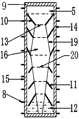
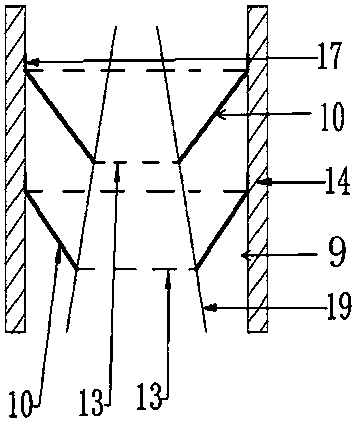
[0077] The present invention will be further described below in conjunction with the accompanying drawings and embodiments.

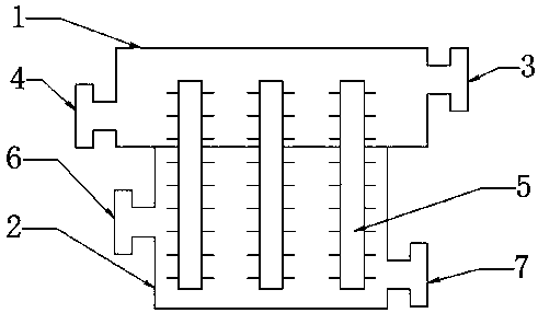
[0078] Such as figure 1 A heat pipe heat exchanger shown includes a heat conduction device 1 , a heating device 2 and a heat pipe 5 .

[0079] The heat conduction device 1 is a metal container made of metal; the appearance shape of the heat conduction device 1 is square.

[0080] Both ends of the heat conduction device 1 have a heat conduction inlet 3 and a heat conduction outlet 4 .

[0081] The heating device 2 is a metal container made of metal; the appearance shape of the heating device 2 is square.

[0082] Both ends of the heating device 2 have a heating inlet 6 and a heating outlet 7 .

[0083] The bottom of the heat conduction device 1 and the top of the heating device 2 are bonded and fixedly connected together, and the heat conduction device 1 and the heating device 2 are independent inner cavities that are not ventilated to each other.

...


PUM


Abstract

The invention discloses a heat pipe type heat exchanger. The heat pipe type heat exchanger comprises a heat conduction device, a heating device and a heat pipe. The heat pipe comprises a metal pipe, a flow guide device, a heat conduction working medium and fins; and the flow guide device which is integrally formed by an evaporation flow guide cover, a condensation flow guide cover and a support is arranged inside the metal pipe. The heat conduction area of a pipe body of the metal pipe of an evaporation section of the heat pipe in the heating device increases the heat conduction heat exchange speed of the heat energy; and the heat conduction heat exchange speed of the heat energy is increased by the pipe body of the metal pipe at the evaporation section of the heat pipe. The metal pipe body, decreasing the heat conduction working medium, of a condensation section of the heat pipe in the heating device increases the heat conduction heat exchange of the heat energy on the condensation section, so that the heat energy on the condensation section of the heat pipe is conveniently to carry out heating and heat conduction on the heat conduction medium outside the heat pipe. Through guide flowing of the heat conduction working medium in the heat pipe by the guide flow device, the heat conduction heat exchange efficiency of the heat energy is improved, and the heat conduction heat exchange speed of the heat energy is expanded.

Description

technical field [0001] The invention relates to a heat exchanger, especially a heat pipe heat exchanger. Background technique [0002] Nowadays, in the processing and production fields of grain, food, chemical industry, medicine, etc., it is necessary to dry the materials to achieve the required moisture content standards. In the process of convection drying, heat energy needs to be converted into hot air through a heat exchanger for use; in the process of vacuum drying, the composite gas produced when the vacuum drying equipment dries materials is 75-98% of water molecules, and the impurities and other gas molecules are mixed together. In combination, the heat exchanger used for condensation is to convert water vapor into liquid in a vacuum state, which can reduce the working power of the vacuum pump. At present, most heat exchangers on the market use heat transfer devices such as tube heat exchangers for heat exchange and heat transfer. The heat transfer speed is slow and...

Claims


Application Information

Patent Timeline
Patent Type & Authority Applications(China)
IPC IPC(8): F28D15/02
CPCF28D15/02
Inventor 冯小川
Owner MENGZHOU YUANHONG DRYING EQUIP RES & DEV CO LTD
Why Eureka
Try Eureka