Heat pipe type vacuum drying box

A technology of vacuum drying oven and drying oven, which is applied in the direction of drying solid materials without heating, drying solid materials, and drying gas arrangement, etc. It can solve the problems of complex internal structure of the heating plate, affecting heat transfer and heat transfer, and uneven drying of materials. , to achieve the effect of improving the compression resistance, increasing the heat conduction effect and accelerating the drying speed

Pending Publication Date: 2019-09-17
MENGZHOU YUANHONG DRYING EQUIP RES & DEV CO LTD
View PDF0 Cites 1 Cited by
  • Summary
  • Abstract
  • Description
  • Claims
  • Application Information

AI Technical Summary

Problems solved by technology

When the heat conduction medium (water, heat transfer oil) in the heating plate of the drying oven and drying room flows and conducts heat in the heating plate for a long time, scale and oil will form on the plate inside the heating plate. The internal structure of the heating plate is complicated, and the inside of the heating plate The scale and oil on the plate body are not easy to clean and descale, and the heating plate with scale and oil will affect the conduction and heat transfer of heat energy
Due to the flow direction of the heat conduction medium in the heating plate, the temperature of the bottom plate of the heating plate and the four corners of the bottom plate and the surrounding areas are uneven, and the uneven temperature of the bottom plate and the four corners of the bottom plate and the surrounding areas of the heating plate causes uneven drying of materials
In some drying ovens and drying rooms, the hot air from the external heat exchange directly dries the materials, which may cause the hidden danger of the materials being polluted.

Method used


Image

  • Heat pipe type vacuum drying box
  • Heat pipe type vacuum drying box
  • Heat pipe type vacuum drying box

Examples


Embodiment 1

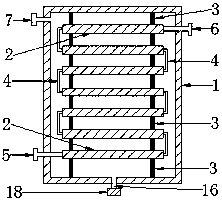
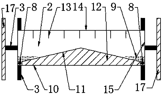
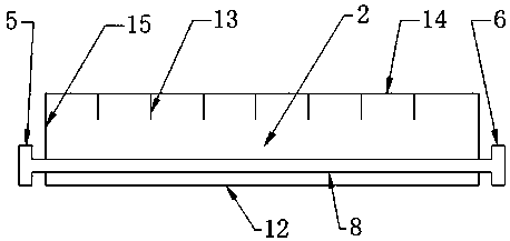
[0083] Such as figure 1 , figure 2 A heat pipe type vacuum drying oven shown includes a drying oven 1 , a heating device 2 , a bracket 3 , a heat pipe 4 , and a drain valve 18 .

[0084] There is a heat energy inlet 5, a heat energy outlet 6, an exhaust port 7 and a drain port 16 on the drying box 1.

[0085] The casing 17 of the drying oven 1 is formed by stamping, folding and welding of steel plates, and the outer surface of the casing 17 has an insulating layer for insulation.

[0086] The door seal of the chamber door of drying box 1 adopts silicon rubber strip to seal, and chamber door is provided with the window that can be used for observation.

[0087] A heat-pipe vacuum drying oven in Example 1 uses a vacuum low-temperature drying process to dry materials.

[0088] There is a water drain 16 on the bottom surface of the drying box 1 .

[0089] The drain valve 18 is installed on the drain 16 outside the drying box 1 .

[0090] After the drying box 1 dries the mate...

Embodiment 2

[0142] The heat pipe type vacuum drying oven of the present invention comprises a drying oven 1 , a heating device 2 , a bracket 3 and a heat pipe 4 .

[0143] The combination structure of the heat pipe vacuum drying oven in Embodiment 2 and the heat pipe vacuum drying oven introduced in Embodiment 1 will not be repeated here.

[0144] A heat-pipe vacuum drying oven in Example 2 uses an air convection drying process to dry materials.

[0145] There is a heat energy inlet 5, a heat energy outlet 6, an exhaust port 7 and a drain port 16 on the drying box 1.

[0146] There is no drain valve installed on the drain port 16 of the drying box 1 .

[0147] A blower fan is installed on the exhaust port 7 of the drying box 1 .

[0148] The air outside the drying box 1 enters the inside of the drying box 1 through the drain port 16 of the drying box 1; the function of the air is to carry moisture.

[0149] The air carries the moisture generated when the material in the drying box 1 is...


PUM


Abstract

The invention discloses a heat pipe type vacuum drying box. The heat pipe type vacuum drying box comprises a drying box body, a heating device, a support and a water draining valve. A heat energy inlet, a heat energy outlet, an exhaust opening and a water draining opening are formed in the drying box boxy, the water draining valve is arranged on the water draining opening of the outer face of the drying box, the heating device is fixedly mounted on a box main body of the drying box body through the support, and the heating device comprises a top plate, a bottom plate, side plates, a heating pipe, a fixed strip, and a heat conduction working medium, the heat conduction working medium rapidly transmits the heat to the top plate and the bottom plate of the heating device through the gas and liquid phase change, balance temperature on the four corners and the periphery of the top plate and the bottom plate of the heating device ensures the material water drying uniformity, the upper and the lower of the heating device carry out simultaneous heating, the heat conduction and exchange speed of the heat energy is improved, the material drying speed is improved, and the heat working media cannot generate water scale and oil scale in the heating device, and the heat pipe type vacuum drying box flexibly selects vacuum low-temperature drying or air convection drying.

Description

technical field [0001] The invention relates to a drying oven, in particular to a heat pipe type vacuum drying oven. Background technique [0002] At present, the main heating method of drying ovens or drying rooms on the market is to pass a flowing heat transfer medium into the heating plate. The heat transfer medium in the heating plate transfers heat to the material in the tray through the heating plate, and the material absorbs heat to evaporate its water. Gasification, water vapor is drawn away by the exhaust device. When the heat conduction medium (water, heat transfer oil) in the heating plate of the drying oven and drying room flows and conducts heat in the heating plate for a long time, scale and oil will form on the plate inside the heating plate. The internal structure of the heating plate is complicated, and the inside of the heating plate The scale and grease on the plate body are not easy to clean and descale, and the heating plate with scale and grease will a...

Claims


Application Information

Patent Timeline
Patent Type & Authority Applications(China)
IPC IPC(8): F26B9/06F26B5/04F26B21/00F26B23/10F26B25/00
CPCF26B5/04F26B9/06F26B21/00F26B23/10F26B25/00
Inventor 冯小川
Owner MENGZHOU YUANHONG DRYING EQUIP RES & DEV CO LTD
Why Eureka
Try Eureka