Heat pipe heating type disc dryer

A disc dryer and heating technology, applied in the direction of heating devices, drying solid materials, dry cargo handling, etc., can solve the problems affecting the dryer, insufficient effective heating area of ​​the heating plate, and speed up the moving speed of materials, etc., to ensure smoothness Effect

Pending Publication Date: 2020-02-25
MENGZHOU YUANHONG DRYING EQUIP RES & DEV CO LTD
View PDF0 Cites 0 Cited by
  • Summary
  • Abstract
  • Description
  • Claims
  • Application Information

AI Technical Summary

Problems solved by technology

In order to prevent high-moisture materials from being clamped between the two rakes and rotate with the rakes, or to speed up the moving speed of the material, the distance between the rakes or the length of the scraper is intentionally increased, resulting in the material ring coverage area being even smaller than the exposed area , the effective heating area of ​​the heating plate is less than 50%, which seriously affects the normal performance of the dryer

Method used


Image

  • Heat pipe heating type disc dryer
  • Heat pipe heating type disc dryer
  • Heat pipe heating type disc dryer

Examples


Embodiment 1

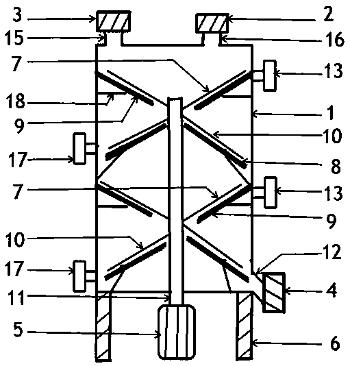
[0108] Such as figure 1 , figure 2 , image 3 , Image 6 A heat pipe heating type disc dryer is shown, including a drying chamber 1, an exhaust device 2, a feeding device 3, an unloading device 4, a variable speed motor 5, a support frame 18, a small heating plate 8, and a large heating plate 9, the lower rake bar 10, the transmission shaft 11, the upper rake bar 7, and the bracket 6.

[0109] The described drying bin 1 is supported and fixed on the ground by a bracket 6 .

[0110] The drying bin 1 includes a material inlet 15, a material outlet 12, an exhaust port 16, and a water outlet.

[0111] The condensed water flowing down from the chamber body in the drying chamber 1 is discharged from the drying chamber 1 through the vacuum drain valve installed on the water outlet.

[0112] The feeding device 3 is installed on the feeding port 15 of the drying bin 1 .

[0113] The feeding device 3 is a highly airtight air-tight device, the material to be dried is transported ...

Embodiment 2

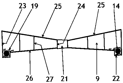
[0195] Such as figure 2 , Figure 5 , Image 6 , Figure 8 , Figure 9 A heat pipe heating type disc dryer is shown, including a drying bin 1, an exhaust device 2, a feeding device 3, a variable speed motor 5, a support frame 18, a small heating plate 8, a large heating plate 9, and a lower rake bar 10, drive shaft 11, upper rake bar 7, bracket 6.

[0196] Such as Figure 9 The structure of the heat-pipe-heated tray dryer shown in Embodiment 2 is the same as the heat-pipe-heated tray dryer introduced in Embodiment 1, and the introduction will not be repeated.

[0197] Such as Figure 9 , Figure 8 When the material drying process of the heat pipe heating type disc dryer shown is a convective drying process: the discharge port 12 of the drying bin 1 is open.

[0198] The air outside the drying bin 1 can enter the inside of the drying bin 1 through the outlet 12 of the drying bin 1 .

[0199] The exhaust device 2 is installed at the exhaust port 16 of the drying chambe...


PUM


Abstract

The invention discloses a heat pipe heating type disk dryer. The heat pipe heating type disk dryer includes a drying bin, an air exhaust device, a feeding device, a variable speed motor, a support frame, a small heating plate, a large heating plate, a lower rake rod, a transmission shaft, an upper rake rod, and a support. The material drying process of the heat pipe heating type disc dryer is a vacuum drying process or a convection drying process. A heat-conducting working medium carries thermal energy and performs heat conduction and heat exchange to the material through top plates of the large heating plate and the small heating plate. The material on the top plate of the heating plate of the large heating plate conveniently moves from the top plate which is higher on the outside and lower on the inside in an internal rotation mode from the outside to the inside, and the material on the top plate of the heating plate of the small heating plate conveniently moves from the top plate which is higher in the inside and lower on the outside in an external rotation mode from the inside to the outside; the material is covered on the top plates of the large heating plate and the small heating plate under the guidance and diversion paving of a rake blade device, the upper and lower heating intensities of the material are improved, drying uniformity of the material water content is improved, and the effective heating area of the top plates of the large heating plate and the small heating plate are greater than 90%.

Description

technical field [0001] The invention relates to a disc dryer, in particular to a heat pipe heating disc dryer. Background technique [0002] The heating discs installed in the disc dryers currently on the market are multi-layered, and the dried materials are dried on the heating discs through alternate internal rotation or external rotation. The heating plate of the disc dryer uses heat conduction to provide heat to the material. Due to the large internal space of the heating plate, the heat transfer medium around the heating plate flows slowly or does not flow, and the heat conduction medium on the top plate around the heating plate The heat is less, so that the materials on the top plate around the inner periphery of the heating plate cannot receive sufficient heat to dry. After the heat transfer medium flows in the heating plate for a long time, it is easy to generate scale and oil. The internal structure of the heating plate is complicated and it is not easy to clean th...

Claims


Application Information

Patent Timeline
Patent Type & Authority Applications(China)
IPC IPC(8): F26B17/22F26B23/10F26B25/00F26B25/04
CPCF26B17/22F26B23/10F26B25/00F26B25/002F26B25/04
Inventor 程广发孟占
Owner MENGZHOU YUANHONG DRYING EQUIP RES & DEV CO LTD
Why Eureka
Try Eureka