Heat-pipe type three-cylinder dryer

A technology of heat pipe type and drying machine, which is applied in non-progressive drying machines, dryers, drying solid materials, etc., can solve the problems of low heat exchange efficiency of heat energy, uneven drying moisture, etc. Optimize the drying effect of materials and the effect of reasonable layout

Active Publication Date: 2016-11-09
龙南县赣钇精细化工有限公司
View PDF4 Cites 1 Cited by
  • Summary
  • Abstract
  • Description
  • Claims
  • Application Information

AI Technical Summary

Problems solved by technology

[0002] Now on the market, there are drying equipment for materials such as grain, chemical products, coal, gravel, sand, mineral products, pasture, crops, and local specialties. The heat exchange outside the equipment of the three-cylinder dryer on the market is hot air, and the heat exchange The heat efficiency is low, the use of heat energy is one-time, and the heat energy required for drying will increase a lot, which will affect the uneven drying moisture of materials

Method used


Image

  • Heat-pipe type three-cylinder dryer
  • Heat-pipe type three-cylinder dryer
  • Heat-pipe type three-cylinder dryer

Examples


Embodiment 1

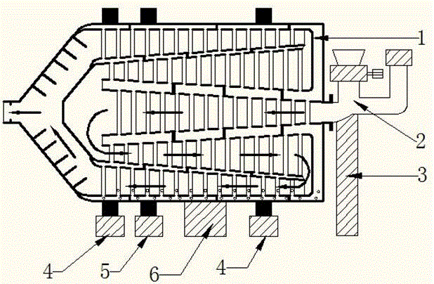
[0049] Such as figure 1 The heat pipe type three-cylinder dryer type A shown includes a heat pipe type three-cylinder drying chamber (1), feeding and exhausting device (2), support (3), idler support (4), driving device (5), heating device (6).

[0050] The heat pipe type three-cylinder dryer type A is fixed after installation.

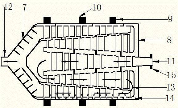
[0051] Such as figure 1 , figure 2 The shown heat pipe type three-tube drying bin (1) includes a casing (8), a composite drying bin (7), a raceway (9), a gear ring (10), and a heat-conducting medium (14).

[0052] The heat pipe type three-cylinder drying bin (1) has a material inlet (11) and a material outlet (12).

[0053] There is a flange joint (15) on the feed inlet (11) of the heat pipe type three-cylinder drying bin (1).

[0054] The composite drying chamber (7) includes an inner cylinder, an outer cylinder, a middle cylinder, a bracket, a baffle, a cooling pipe, and a deflector.

[0055] The heat-conducting medium (14) is in the cavity b...

Embodiment 2

[0084] Such as Figure 5 A heat pipe type three-cylinder dryer type B shown includes a heat pipe type three-cylinder drying chamber (1), a feeding exhaust device (2), a support (3), a roller support (4), and a driving device (5) , heating device (6), mobile device (21).

[0085] The combination structure of the heat pipe type three-cylinder drying chamber type B introduced in the second embodiment and the heat pipe type three-cylinder dryer type A introduced in the embodiment 1 will not be repeated in the embodiment 2.

[0086] Such as Figure 5 The heat pipe type three-cylinder dryer type B shown is different from the heat pipe type three-cylinder dryer type A introduced in Example 1 in that the heat pipe type three-cylinder dryer B adds a moving device (21).

[0087] The mobile device (21) is a platform made of metal with wheels (22).

[0088] The heat-pipe three-cylinder drying machine type B has a heat-pipe three-cylinder drying chamber (1), a bracket (3), a roller supp...


PUM


Abstract

The invention discloses a heat-pipe type three-cylinder dryer comprising a heat-pipe type three-cylinder drying bin, a feeding exhaust device, a support, a heating device, a driving device, a roller rack and a moving device. The heat-pipe type three-cylinder drying bin comprises a shell, a combined-type drying bin, 2-5 sets of roller paths, 1-2 sets of gear rings and a heat-conducting medium; the heat-conducting medium is in the inner cavity between the shell and the combined-type drying bin; the feeding exhaust device comprises a vacuum feeding and discharging device, a ventilation pipe and an exhaust device; the roller paths and the gear rings are arranged on the shell of the heat-pipe type three-cylinder drying bin. Under the driving of the driving device, the heat-pipe type three-cylinder drying bin can rotate to operate under the support of rollers on the roller rack; materials are fed or discharged from the heat-pipe type three-cylinder drying bin through the vacuum feeding and discharging device, humidity is discharged from the combined-type drying bin through the exhaust device, and the materials can be continuously dried, so that drying efficiency of the materials is improved, and drying effect of the materials is optimized.

Description

technical field [0001] The invention relates to a three-cylinder dryer, in particular to a heat pipe type three-cylinder dryer. Background technique [0002] Now on the market, there are drying equipment for materials such as grain, chemical products, coal, gravel, sand, mineral products, pasture, crops, and local specialties. The heat exchange outside the equipment of the three-cylinder dryer on the market is hot air, and the heat exchange The heat efficiency is low, the use of heat energy is one-time, and the heat energy required for drying will increase a lot, which will affect the uneven drying moisture of materials. [0003] The patented heat pipe type three-cylinder vacuum dryer (patent application number 2016208123269) that I applied for includes a heat pipe type three-cylinder drying chamber, an air duct, a bracket, a vacuum unit, a heating device, a driving device, a vacuum feeding and discharging device, and a moving device. The vacuum feeding and discharging devi...

Claims


Application Information

Patent Timeline
Patent Type & Authority Applications(China)
IPC IPC(8): F26B11/04F26B25/16F26B23/10F26B25/00F26B25/02
CPCF26B11/022F26B11/026F26B11/0404F26B11/045F26B23/10F26B25/005F26B25/16
Inventor 张海娟
Owner 龙南县赣钇精细化工有限公司
Why Eureka
Try Eureka