Earth fault positioning method for electric power circuit

A technology of ground fault and positioning method, which is applied in the direction of fault location, fault detection according to conductor type, fault detection by pulse reflection method, etc. It can solve the problems of inability to obtain cable fault type, inaccurate fault location, and small workload, etc., to achieve The effect of reducing deviation, accurate fault distance and reducing workload

Inactive Publication Date: 2019-09-17
ZIBO WINNER ELECTRIC
View PDF0 Cites 9 Cited by
  • Summary
  • Abstract
  • Description
  • Claims
  • Application Information

AI Technical Summary

Problems solved by technology

The low-voltage pulse method can solve the above-mentioned various fault detection problems, and can perform fault location, with low difficulty and small workload, and will not affect the reliability of power supply. However, this method is not accurate enough for fault location during detection, and it is impossible to obtain cable type of failure

Method used


Image

  • Earth fault positioning method for electric power circuit
  • Earth fault positioning method for electric power circuit
  • Earth fault positioning method for electric power circuit

Examples


Embodiment 1

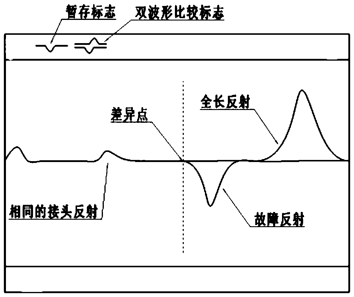
[0026] Such as Figure 1-2 A method for locating a ground fault in a power line as shown, specifically includes the following steps:

[0027] Step 1: Query and obtain the location of the substation of the power supply line, and use the discharge rod to fully discharge the phase lines of the cable to the ground;

[0028] Step 2, connect the plug of the low-voltage pulse test line to the low-voltage pulse socket of the test device, and connect the two clamps of the test line to the two faulty phase lines;

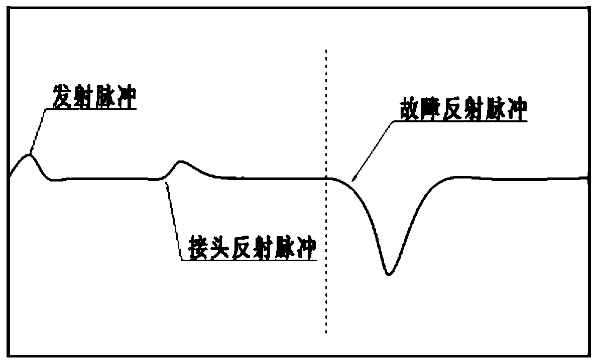
[0029] Step 3. Set the appropriate wave velocity according to the type of cable, and inject a low-voltage pulse into the test cable through the low-voltage pulse test line. The pulse propagates along the cable and encounters an impedance mismatch point. The pulse is reflected and sent back to the measurement point to be recorded by the test device. ;

[0030] Step 4: Timing is performed when the low-voltage pulse is transmitted. When the reflected pulse at the impedance mis...

Embodiment 2

[0038] On the basis of Embodiment 1, further, in the process of displaying the reflected pulse waveform, the gain of the pulse waveform can also be adjusted to improve the display accuracy of the reflected pulse waveform, which specifically includes the following steps:

[0039] Connect the plug of the low-voltage pulse test line to the low-voltage pulse socket of the test device, and connect the two clamps of the test line to the two faulty phase lines;

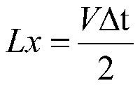
[0040] Set the appropriate wave velocity according to the type of cable, and inject a low-voltage pulse into the test cable through the low-voltage pulse test line. The pulse propagates along the cable and encounters an impedance mismatch point, and the pulse is reflected. Timing is carried out when the pulse is transmitted. When the reflected pulse at the impedance mismatch point is received, it is counted as △t, and the propagation speed of the pulse traveling wave is counted as V. Then the fault point distance Lx is:

[0...

Embodiment 3

[0048] On the basis of Embodiment 2, the polarity of the reflected pulse of the disconnection fault is the same as that of the transmitted pulse, and the reflected pulse of the short-circuit mixed line fault is opposite to the polarity of the transmitted pulse. Therefore, by identifying the polarity of the reflected pulse, the nature of the fault can be determined;

[0049] Such as figure 1 As shown, the waveform at the fault is downward, so it is judged as a short-circuit fault, and if the waveform is upward, it is a disconnection fault;

[0050] When carrying out specific application, include the following steps:

[0051] Connect the plug of the low-voltage pulse test line to the low-voltage pulse socket of the test device, and connect the two clamps of the test line to the two faulty phase lines. A low-voltage pulse, the pulse travels along the cable and encounters an impedance mismatch point, the pulse is reflected, returned to the measurement point and recorded by the te...


PUM


Abstract

The invention discloses an earth fault positioning method for an electric power circuit, and particularly relates to the technical field of electric power system fault positioning. The method specifically comprises the following steps that: S1: inquiring and obtaining the transformer substation position of a power supply circuit, and utilizing a discharging rod to enable each phase line of a cable to fully discharge to the earth; S2: connecting the plug of a low-voltage pulse test line with a low-voltage pulse socket of a test device, and connecting two clamp forceps of the test line with two fault phase lines; and S3: according to the type of the cable, setting proper wave velocity, and through the low-voltage pulse test line, injecting a low-voltage pulse into a test cable. A fault distance and fault positioning obtained by the method can be more accurate, a deviation with a practical fault point can be lowered to improve fault positioning accuracy, the property of the fault can be judged through the identification of the polarity of a reflected pulse, the workload of a user when electric power circuit fault detection is carried out can be lowered, and in addition, the method is simple in operation and high in accuracy.

Description

technical field [0001] The invention relates to the technical field of power system fault location, and more specifically, the invention relates to a power line ground fault location method. Background technique [0002] At present, the distribution network in our country adopts the non-direct grounding method of neutral point (NUGS). Since the current flowing through the grounding point is small when a grounding fault occurs, it is called a small current grounding system. The small current grounding system can be divided into the neutral point ungrounded system (NUS), the neutral point through the resistance grounding system (NRS) and the neutral point through the arc suppression coil grounding system (NES). When a ground fault occurs, since the three line voltages are still symmetrical, especially in the system where the neutral point passes through the arc suppression coil, the current flowing through the ground point is very small, which does not affect the continuous po...

Claims


Application Information

Patent Timeline
Patent Type & Authority Applications(China)
IPC IPC(8): G01R31/08G01R31/11G01R31/02
CPCG01R31/085G01R31/088G01R31/11G01R31/50Y04S10/52
Inventor 王宜波韩仁章
Owner ZIBO WINNER ELECTRIC
Why Eureka
Try Eureka