
Wafer bonding equipment and method

A wafer bonding and wafer technology, applied in semiconductor devices, electrical components, circuits, etc., can solve problems such as errors, inability of the lens and upper chuck to move relative to each other, and unclear alignment marks on the read wafer , to achieve the effect of improving the accuracy

Active Publication Date: 2021-06-15
WUHAN XINXIN SEMICON MFG CO LTD
View PDF10 Cites 1 Cited by
  • Summary
  • Abstract
  • Description
  • Claims
  • Application Information

AI Technical Summary

Problems solved by technology

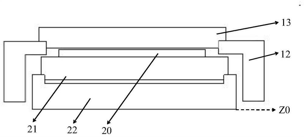
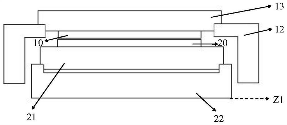
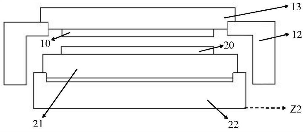
[0004] After the existing technology, the upper and lower lenses are calibrated to determine the distance between the upper and lower lenses. It is manually adjusted to read the calibration mark of the same wafer, which can be read in the depth of field of the lens, and there is an error compared with the standard focal length; resulting in When the integrated lens reads the alignment mark of the lower wafer most clearly, it often reads the alignment mark of the upper wafer in the back and is not clear
Moreover, since the upper chuck cannot move vertically in the Z-axis direction, the lens and the upper chuck cannot move relative to each other when reading the alignment mark of the upper wafer. The alignment marks are not clear

Method used


Image

  • Wafer bonding equipment and method
  • Wafer bonding equipment and method
  • Wafer bonding equipment and method

Examples


Embodiment Construction

[0049] The following will clearly and completely describe the technical solutions in the embodiments of the present invention with reference to the accompanying drawings in the embodiments of the present invention. Obviously, the described embodiments are only some, not all, embodiments of the present invention. Based on the embodiments of the present invention, all other embodiments obtained by persons of ordinary skill in the art without creative efforts fall within the protection scope of the present invention.

[0050] It should be noted that, in the case of no conflict, the embodiments of the present invention and the features in the embodiments can be combined with each other.

[0051] The present invention will be further described below in conjunction with the accompanying drawings and specific embodiments, but not as a limitation of the present invention.

[0052] The present invention includes a wafer bonding apparatus, such as Figure 5 shown, including:

[0053] ...


PUM


Abstract

The present invention relates to the technical field of semiconductor manufacturing, in particular to a wafer bonding equipment, including: a first fixing device that can only move along the X-axis and Y-axis directions, and is used to fix the first wafer to be bonded. A wafer is provided with a first calibration mark; a reference mark is set on the first fixing device; a second fixing device movable along the X axis, Y axis, and Z axis is arranged opposite to the first fixing device; the rotation device , arranged on the side of the second fixing device facing the first fixing device, for fixing a second wafer to be bonded, and a second calibration mark is provided on the second wafer; for the oppositely arranged and synchronous along the X-axis 1, Y-axis, and Z-axis moving image capture devices are respectively used to capture the first calibration mark and the second calibration mark; a reference mark capture device is used to read the reference mark. Beneficial effects: it can ensure that the image acquisition device can clearly capture the first calibration mark and the second calibration mark at the same time, thereby improving the wafer bonding precision.

Description

technical field [0001] The invention relates to the technical field of semiconductor manufacturing, in particular to a wafer bonding device and method, so as to improve the precision of wafer bonding. Background technique [0002] Wafer alignment is the most critical factor affecting the bonding accuracy in the wafer bonding process. Wafer alignment is mainly composed of the mechanical movement of the chuck (Table) that fixes the wafer and reading the alignment mark (Mark) on the wafer. ) lens to obtain wafer coordinates together to achieve. [0003] The two bonded wafers are divided into upper wafer and lower wafer, and the lenses for reading the alignment marks of the two wafers are divided into independent type and integrated type. The stand-alone type is to read the lenses of the upper wafer and the lower wafer are independent of each other, and finally convert the mark coordinates acquired by the two lenses into a coordinate system to calculate the relative position of...

Claims


Application Information

Patent Timeline
Patent Type & Authority Patents(China)
IPC IPC(8): H01L21/60H01L21/68
CPCH01L21/681H01L24/76H01L24/82H01L2224/76001H01L2224/76753H01L2224/8213
Inventor 陶超
Owner WUHAN XINXIN SEMICON MFG CO LTD
Learn More