One-side bonding method and application of cemented carbide strips suitable for cemented carbide hard surface processing
A technology of hard alloy and alloy strips, which is applied in metal processing equipment, earth drilling, manufacturing tools, etc. It can solve the problems of high cost, low efficiency when cemented carbide strips are bonded, and unguaranteed accuracy, and achieves convenient operation. , Guarantee the bonding quality and the effect of excellent quality
- Summary
- Abstract
- Description
- Claims
- Application Information
AI Technical Summary
Problems solved by technology
Method used
Image
Examples
Embodiment 1
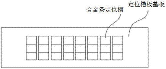
[0053] This embodiment provides a positioning groove plate suitable for bonding cemented carbide strips in cemented carbide hard surface processing, and its structural schematic diagram is shown in the attached figure 1 shown. The positioning slot plate includes a base plate and an alloy bar positioning slot arranged on the base plate, and the size of the alloy bar positioning slot matches the size of the cemented carbide bar.
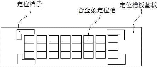
[0054] The base plate of the positioning groove plate and the positioning groove are an integrated structure, and the depth of the alloy strip positioning groove on the substrate is not greater than the thickness of the hard alloy strip. After placing an appropriate amount of hard alloy strips on the positioning groove plate, most of the hard alloy strips fall into the positioning grooves one by one, and the individual positioning grooves that do not fall into the hard alloy strips can be placed manually. The cemented carbide strips are swept off the ...
Embodiment 2
[0057] Based on the positioning groove plate described in Embodiment 1, this embodiment provides a bonding method suitable for cemented carbide strips in the processing of cemented carbide hard surfaces. The schematic diagram of the process flow is shown in the attached Figure 4 shown. The method comprises the steps of:
[0058] S1. Prepare the positioning groove plate;
[0059] S2. Put the hard alloy strip on the positioning slot plate, place the hard alloy strip on the positioning slot plate as required, and drop the excess hard alloy strip from the positioning slot plate;
[0060] S3. Bond the cemented carbide strip with a perforated tape, so that the cemented carbide strip and one side of the tape are firmly bonded;
[0061] This embodiment adopts single-sided adhesive tape (adhesive tape has only one side to use the adhesive material), so that the side of the adhesive tape with glue is bonded firmly with the cemented carbide strip;
[0062] S4. Fix the cemented carbid...
Embodiment 3
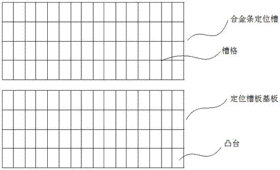
[0074] This embodiment provides another positioning groove plate suitable for bonding cemented carbide strips in cemented carbide hard surface processing, and its structural schematic diagram is shown in the attached image 3 shown. The positioning slot plate includes a base plate and an alloy bar positioning slot arranged on the base plate, and the size of the alloy bar positioning slot matches the size of the cemented carbide bar.
[0075] The positioning slot plate includes a base plate and an alloy bar positioning slot arranged on the base plate. The base plate is composed of several liftable bosses, and the alloy bar positioning slot is a grid composed of several hollowed out slots. Only one tungsten carbide strip can be accommodated in the center; the boss can rise or fall from the corresponding slot hole position; the size of the boss and the slot match and match the size of the tungsten carbide strip . First, make the boss in the initial state, and the plane formed b...
PUM
 Abstract
Description
Claims
Application Information
 - R&D
- Intellectual Property
- Life Sciences
- Materials
- Tech Scout
- Unparalleled Data Quality
- Higher Quality Content
- 60% Fewer Hallucinations
Browse by: Latest US Patents, China's latest patents, Technical Efficacy Thesaurus, Application Domain, Technology Topic, Popular Technical Reports.
© 2025 PatSnap. All rights reserved.Legal|Privacy policy|Modern Slavery Act Transparency Statement|Sitemap|About US| Contact US: help@patsnap.com


