Adjustable bearing machining fixing device

A bearing processing and fixing device technology, which is applied in the field of bearing processing, can solve the problems that the fixing device cannot be adjusted, the scope of application is narrow, and the processing cost is increased, and the effect of increasing the scope of use, reducing the processing cost and accurate processing size can be achieved.

Inactive Publication Date: 2021-03-16
东台立一工业技术有限公司
View PDF8 Cites 0 Cited by
  • Summary
  • Abstract
  • Description
  • Claims
  • Application Information

AI Technical Summary

Problems solved by technology

[0003] The adjustable bearing processing and fixing devices currently on the market realize the processing mode of standardized production and improve the efficiency of bearing processing. However, in the process of use, the fixing devices on the market cannot make corresponding adjustments according to the different sizes of bearings. , a corresponding type of fixing device can only fix and clamp bearings of one size, the scope of application is relatively narrow, it will bring some inconvenience to the processing manufacturer, and the processing cost will increase accordingly, so it is necessary to build on this basis make further improvements

Method used


Image

  • Adjustable bearing machining fixing device
  • Adjustable bearing machining fixing device
  • Adjustable bearing machining fixing device

Examples


Embodiment 1

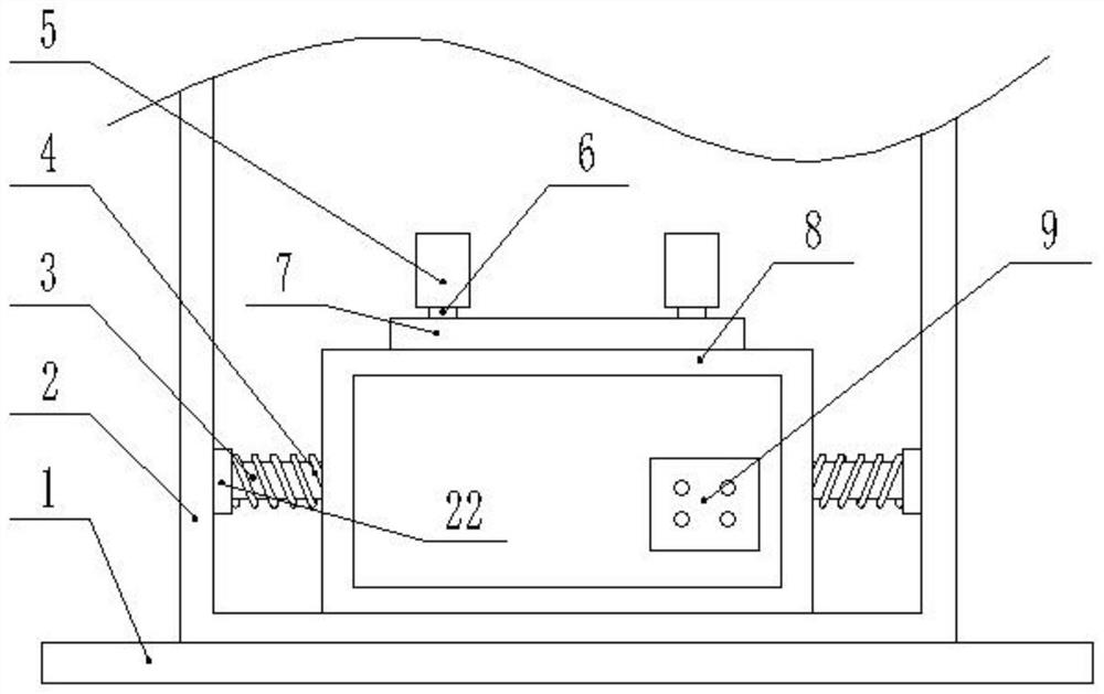
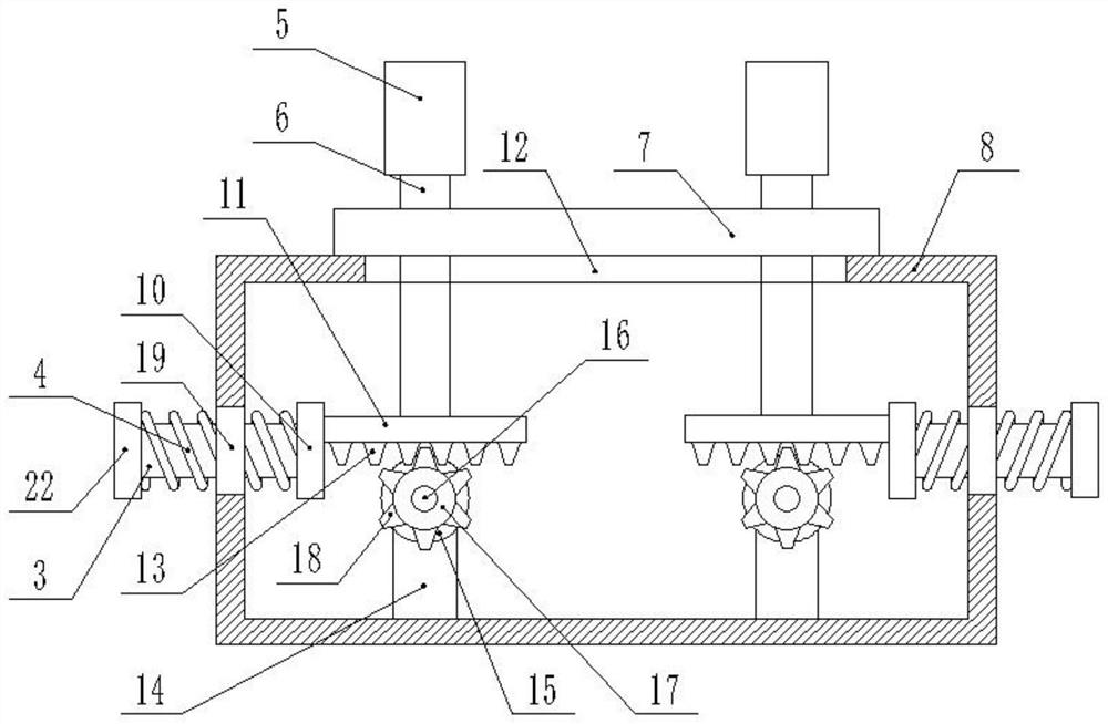
[0022] Such as Figure 1-4 As shown, in the embodiment of the present invention, an adjustable bearing processing and fixing device includes a box body 2, fixed plates 22 are symmetrically installed on the left and right inner walls of the box body 2, and telescopic rods 3 are connected to the fixed plate 22, so that A work box 8 is provided inside the box body 2, a chute 12 is provided in the middle of the upper end surface of the work box 8, a workbench 7 is provided at the upper end of the work box 8, and a rectangular groove 21 is provided in the middle of the workbench 7, The front portion of the working box 8 is provided with a control switch 9, the output end of the control switch 9 is electrically connected to the input end of the motor 15, by opening the control switch 9, the motor 15 is started to work, which improves the degree of mechanization of the device , the left and right inner walls of the working box 8 are provided with holes 19, the telescopic rod 3 passes...

Embodiment 2

[0025] The present invention also provides another embodiment. The difference between this embodiment and the above-mentioned embodiment is that: the bottom of the box body 2 is provided with a base 1, and the base 1 is welded to the box body 2, so that the device can The work is more stable when performing machining operations.

[0026] The working principle of the present invention is:

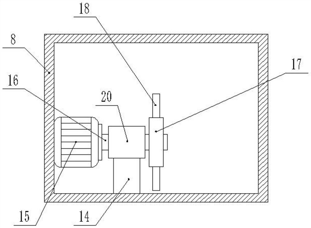
[0027] In this embodiment, the bearings to be processed are placed on the workbench 7, the control switch 9 is turned on, and the motor 15 is controlled to rotate through the control switch 9. The motor 15 drives the rotating shaft 16 to rotate, and the rotating shaft 16 drives the rotating disk 17. Rotate the rotating tooth 18 on the rotating disk 17 to follow the rotation of the rotating disk 17, because the rotating tooth 18 and the moving tooth 13 mesh with each other, the rotating tooth 18 can then drive the moving tooth 13 to move left and right, and then drive the moving plate 11 to m...


PUM


Abstract

The invention relates to the technical field of bearing machining, in particular to an adjustable bearing machining fixing device. The adjustable bearing machining fixing device comprises a box body,wherein fixing discs are symmetrically arranged on the left inner wall and the right inner wall of the box body; telescopic rods are connected to the fixing discs; a working box is arranged in the boxbody; hole grooves are formed in the left inner wall and the right inner wall of the working box; the telescopic rods penetrate through the hole grooves to be connected to connecting plates; a movable plate is connected to each connecting plate; the upper end of the movable plate penetrates through the upper end face of the working box to be provided with a connecting rod; a fixing clamp is connected to the connecting rod; movable teeth are arranged at the lower end of the movable plate; fixing bases are arranged in the working box; a lantern ring is arranged at the upper end of each fixing base; motors are arranged on the rear portion of the inner side of the working box; transmission shafts are rotatably connected to the motors; rotating discs are rotatably connected to the transmissionshafts; rotating teeth are uniformly distributed on the rotating discs; the problem that the device is single in machining is solved; the application range is enlarged; the sliding phenomenon of a bearing can be prevented in the machining process; and the machining size is more accurate.

Description

technical field [0001] The invention relates to the technical field of bearing processing, in particular to an adjustable fixing device for bearing processing. Background technique [0002] Bearings are used to determine the relative movement position of the rotating shaft and other parts, and play a supporting or guiding role. Its main function is to support the mechanical rotating body to reduce the mechanical load friction coefficient of the equipment during the transmission process. According to the moving elements Different friction properties, bearings can be divided into rolling bearings and sliding bearings. [0003] The adjustable bearing processing and fixing devices currently on the market realize the processing mode of standardized production and improve the efficiency of bearing processing. However, in the process of use, the fixing devices on the market cannot make corresponding adjustments according to the different sizes of bearings. , a corresponding type o...

Claims


Application Information

Patent Timeline
Patent Type & Authority Applications(China)
IPC IPC(8): B24B41/02B24B41/06B23Q3/06
CPCB24B41/067B24B41/02B23Q3/06
Inventor 韩建
Owner 东台立一工业技术有限公司
Why Eureka
Try Eureka