A hard surface processing method of screw drilling tool and a device for realizing the method

A technology of screw drilling tools and processing methods, which is applied to drill pipes, drill pipes, drilling equipment and other directions, can solve the problems of high cost, low efficiency, inability to guarantee accuracy, etc., and achieve good compactness, reduce costs, and improve bonding accuracy. degree of effect

Active Publication Date: 2017-08-25
株洲金韦硬质合金有限公司
View PDF5 Cites 0 Cited by
  • Summary
  • Abstract
  • Description
  • Claims
  • Application Information

AI Technical Summary

Problems solved by technology

At the same time, aiming at the defects of low efficiency, high cost and unguaranteed precision when bonding hard-faced carbide strips of TC bearings, a bonding method suitable for cemented carbide strips in hard-faced hard-facing processing of hard alloys is provided. The method is simple and efficient. Efficient, effectively solves the technical defect that the hard alloy strip needs to be placed and pasted manually to complete the hard surface processing of the hard alloy. The hard alloy strip is not square, and the difference between the formed hard alloy strip and the hard alloy strip Welds between are more resistant to erosion

Method used


Image

  • A hard surface processing method of screw drilling tool and a device for realizing the method
  • A hard surface processing method of screw drilling tool and a device for realizing the method
  • A hard surface processing method of screw drilling tool and a device for realizing the method

Examples


Embodiment 1

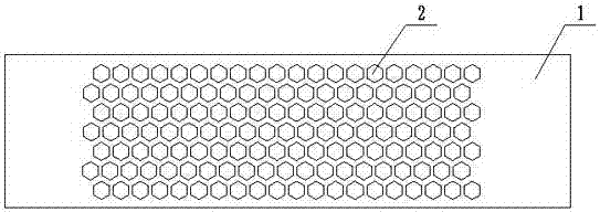
[0047] This embodiment provides a device for machining a cemented carbide layer on the hard surface of a screw drill. The device is a positioning groove plate, and its structural diagram is shown in the attached figure 1 shown. The positioning slot plate includes a base plate 1 and an alloy bar positioning slot arranged on the base plate 1. The alloy bar positioning slot is a slot grid composed of a number of hollowed out slot holes 2, and only one hard metal bar can be accommodated in the slot hole 2. Tungsten carbide strip 3; the size of the slot 2 is adapted to the size of the cemented carbide strip 3; the shape of the slot 2 is hexagonal.

[0048] The positioning groove plate base plate 1 and the positioning groove are an integrated structure, and the depth of the alloy strip positioning groove on the substrate 1 is not greater than the thickness of the hard alloy strip 3 . After placing an appropriate amount of cemented carbide strips 3 on the positioning slot plate, mos...

Embodiment 2

[0051] Based on the positioning groove plate described in Embodiment 1, this embodiment provides a hard surface processing method for screw drilling tools, and the schematic diagram of the process flow is shown in the attached Figure 5 shown. The method comprises the steps of:

[0052] S1. Prepare the positioning groove plate;

[0053] S2. Put the cemented carbide strip 3 on the positioning groove plate, place the cemented carbide strip 3 on the positioning groove plate as required, and drop the excess cemented carbide strip 3 from the positioning groove plate, so that the hard alloy strip 3 Quality alloy strips 3 are evenly arranged on the positioning groove plate;

[0054] S3. bonding the cemented carbide strip 3 with a perforated adhesive tape, so that the cemented carbide strip 3 and one side of the adhesive tape are firmly bonded to form a cemented carbide strip bonding plate including several cemented carbide strips 3;

[0055] This embodiment uses single-sided adhes...

Embodiment 3

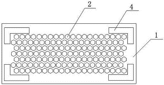
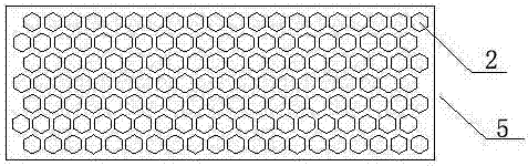
[0064] This embodiment provides another device for machining a cemented carbide layer on the hard surface of a screw drill, and its structural schematic diagram is shown in the attached image 3 and Figure 4 shown. The device is a positioning groove plate, and the positioning groove plate includes a base plate 1 and an alloy strip positioning groove 5 arranged on the base plate 1, such as Figure 4 As shown, the base plate 1 is composed of several liftable bosses 11, such as image 3 As shown, the alloy bar positioning groove 5 is a slot grid composed of several hollowed out slot holes 2, and only one hard alloy bar 3 can be accommodated in the slot hole 2; Rising or falling; the dimensions of the boss 11 and the slot 2 are matched and matched with the size of the hard alloy strip 3; the shape of the slot 2 is hexagonal. First, make the boss 11 in the initial state, and the plane formed by the boss 11 becomes the bottom surface of the groove. After placing an appropriate a...


PUM


Abstract

The invention provides a method for processing the hard surface of a screw drill and a device for realizing the method. The present invention first creatively designs the shape of the cemented carbide strip not to be a square, so that the gap between the cemented carbide strip and the cemented carbide strip is a curved shape, that is, the weld seam is a curved shape, so that when the mud and drilling fluid are eroded, Most of the force is decomposed to the hard alloy strip, which improves the wear resistance of the centralizer and TC bearing. The present invention also provides a positioning groove plate adapted to the rapid formation of the hard surface of the screw drill by the cemented carbide strip, the positioning groove plate is provided with a slot hole, and the shape of the slot hole is not square to match the shape of the cemented carbide strip , the positioning groove plate is used to arrange the carbide strips neatly and evenly according to the requirements, combined with the use of adhesive tape, it is simple and easy to realize the one-time bonding of a large number of cemented carbide strips, which greatly improves the bonding efficiency and improves the safety of manual operation. Different bonding angles, uneven bonding intervals, etc., improve the bonding accuracy, effectively guarantee and improve the wear resistance of the hard surface of the product.

Description

technical field [0001] The invention relates to the technical field of cemented carbide material manufacturing, and more specifically, relates to a method for bonding a large number of small-sized cemented carbides and a device for realizing the method. Background technique [0002] Exploitation drilling tool or screw drilling tool is a volumetric downhole dynamic drilling tool that uses drilling fluid as power and converts fluid pressure energy into mechanical energy. It plays an important role in the drilling field. [0003] Centralizers and TC bearings (radial bearings) are important parts of drilling tools, such as TC bearings, which bear the lateral force generated by the rotation of the drill bit and cardan shaft in the screw drilling tool. The key component of the service life of the tool. [0004] The surfaces of the centralizer and the TC bearing need to be welded or sintered with a large number of hard alloy strips (tungsten carbide blocks) to improve the wear res...

Claims


Application Information

Patent Timeline
Patent Type & Authority Patents(China)
IPC IPC(8): E21B17/10F16B11/00
Inventor 卿林汪文斋刘能文杨荡杨宇
Owner 株洲金韦硬质合金有限公司
Why Eureka
Try Eureka