
An Antenna Double Track Sliding Structure

A sliding structure, dual-track technology, applied to antennas, rotating antennas, folded antennas, etc., can solve the problems of unable to achieve 360-degree rotation, unable to rotate 360-degree of the installation part, unable to achieve the expected effect, etc., to achieve good protection ability, simplified effect of structure

Active Publication Date: 2020-11-20
HANGZHOU ZHIKE TECH CO LTD
View PDF12 Cites 0 Cited by
  • Summary
  • Abstract
  • Description
  • Claims
  • Application Information

AI Technical Summary

Problems solved by technology

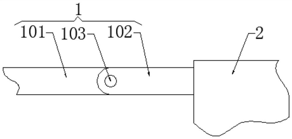
According to the embodiment, the installation part and the installation part can be embedded in the track groove, and the installation part and the installation part are hinged. When the antenna is in the unfolded state, the figure 1 It can be seen from the figure that the installation part is still located in the track groove, so the installation part can only rotate outward along the opening of the track groove, and cannot achieve 360-degree rotation, and the convex column on the outer wall of the second bracket is embedded in the concave hole inside the second track groove. In the groove, the second bracket can only slide along the groove inside the second track groove, and the installation part cannot be rotated 360 degrees. Therefore, this technical solution has defects and cannot achieve the expected effect

Method used


Image

  • An Antenna Double Track Sliding Structure
  • An Antenna Double Track Sliding Structure
  • An Antenna Double Track Sliding Structure

Examples


Embodiment Construction

[0024] The following will clearly and completely describe the technical solutions in the embodiments of the present invention with reference to the accompanying drawings in the embodiments of the present invention. Obviously, the described embodiments are only some, not all, embodiments of the present invention. Based on the embodiments of the present invention, all other embodiments obtained by persons of ordinary skill in the art without making creative efforts belong to the protection scope of the present invention.

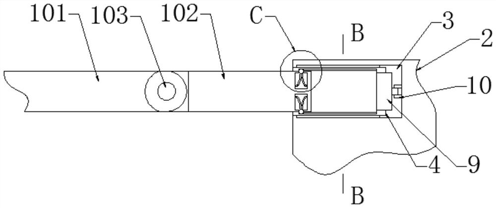
[0025] see Figure 1-5 According to an embodiment of the present invention, an antenna double-track sliding structure is provided, including an antenna 1 and a mounting sleeve 2 for mounting the antenna 1. The antenna 1 includes a peripheral part 101 and a mounting part 102. The peripheral part 101 A micromotor 103 is embedded at one end, and the peripheral part 101 is rotatably connected to one end of the installation part 102 through a first transmission sha...


PUM


Abstract

The invention relates to the field of antennas, and discloses an antenna double-track sliding structure, which includes an antenna and a mounting sleeve for mounting the antenna. The antenna includes an external part and a mounting part, and one end of the external part is embedded A micromotor is provided, and the peripheral part is rotationally connected with one end of the installation part through the first transmission shaft on the micromotor. One end of the installation sleeve is provided with an installation groove, and a sliding sleeve is embedded in the installation groove. The inner wall of the sliding sleeve is symmetrically provided with sliding slots, and the end of the mounting part away from the micro motor extends to the inside of the sliding sleeve. By setting the sliding sleeve inside the mounting sleeve, and the mounting part can be accommodated in the sliding sleeve, the structure of the antenna is simplified. At the same time, the sliding sleeve is rotatably connected with the mounting sleeve through the bearing, and rotates under the drive of the driving motor. , to drive the installation part and the peripheral part to rotate, the installation part can realize 360-degree rotation, and the range of adjustment angle is larger.

Description

technical field [0001] The invention relates to the field of antennas, in particular to an antenna double-track sliding structure. Background technique [0002] The structure of the existing router antenna is basically fixed, which makes the storage of the router inconvenient. It needs to occupy a large space when it is packaged by express delivery, and it is easy to damage the antenna during transportation. At the same time, due to the limitation of the space used, the antenna is The placement angle has limitations, so that the signal strength is affected by the antenna placement angle, and the expected effect cannot be achieved. [0003] The installation part of the product provided by the patent document CN206673086U is slidingly connected with the track groove through the bracket, and one end of the installation part is hinged with the installation part, and the other end is hinged with the peripheral part. Put it at a suitable angle, and the peripheral part can be retr...

Claims


Application Information

Patent Timeline
Patent Type & Authority Patents(China)
IPC IPC(8): H01Q1/08H01Q1/10H01Q3/02H01Q1/22
CPCH01Q1/084H01Q1/10H01Q1/22H01Q3/02
Inventor 许才元
Owner HANGZHOU ZHIKE TECH CO LTD
Learn More