
Circular comb having a comb segment and an aligning segment

A technology of circular combing and carding machines, applied in the direction of combing machines, fiber treatment, textiles and papermaking, etc., which can solve the problems of low carding effect, irregular carding machine, unsatisfactory results, etc.

Active Publication Date: 2019-09-17
STAEDTLER & UHL
View PDF8 Cites 0 Cited by
  • Summary
  • Abstract
  • Description
  • Claims
  • Application Information

AI Technical Summary

Problems solved by technology

The teeth of the second comb segment region are configured such that the combing effect is lower than at the end of the first comb segment region arranged opposite the direction of rotation
[0009] Despite these known solutions, during the bonding process, irregular and unsatisfactory results were often observed in previous cards, especially when these cards were operated at high nip rates

Method used


Image

  • Circular comb having a comb segment and an aligning segment
  • Circular comb having a comb segment and an aligning segment
  • Circular comb having a comb segment and an aligning segment

Examples


Embodiment Construction

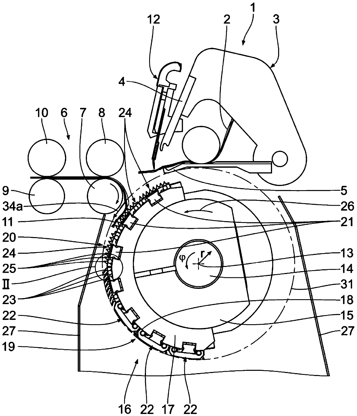
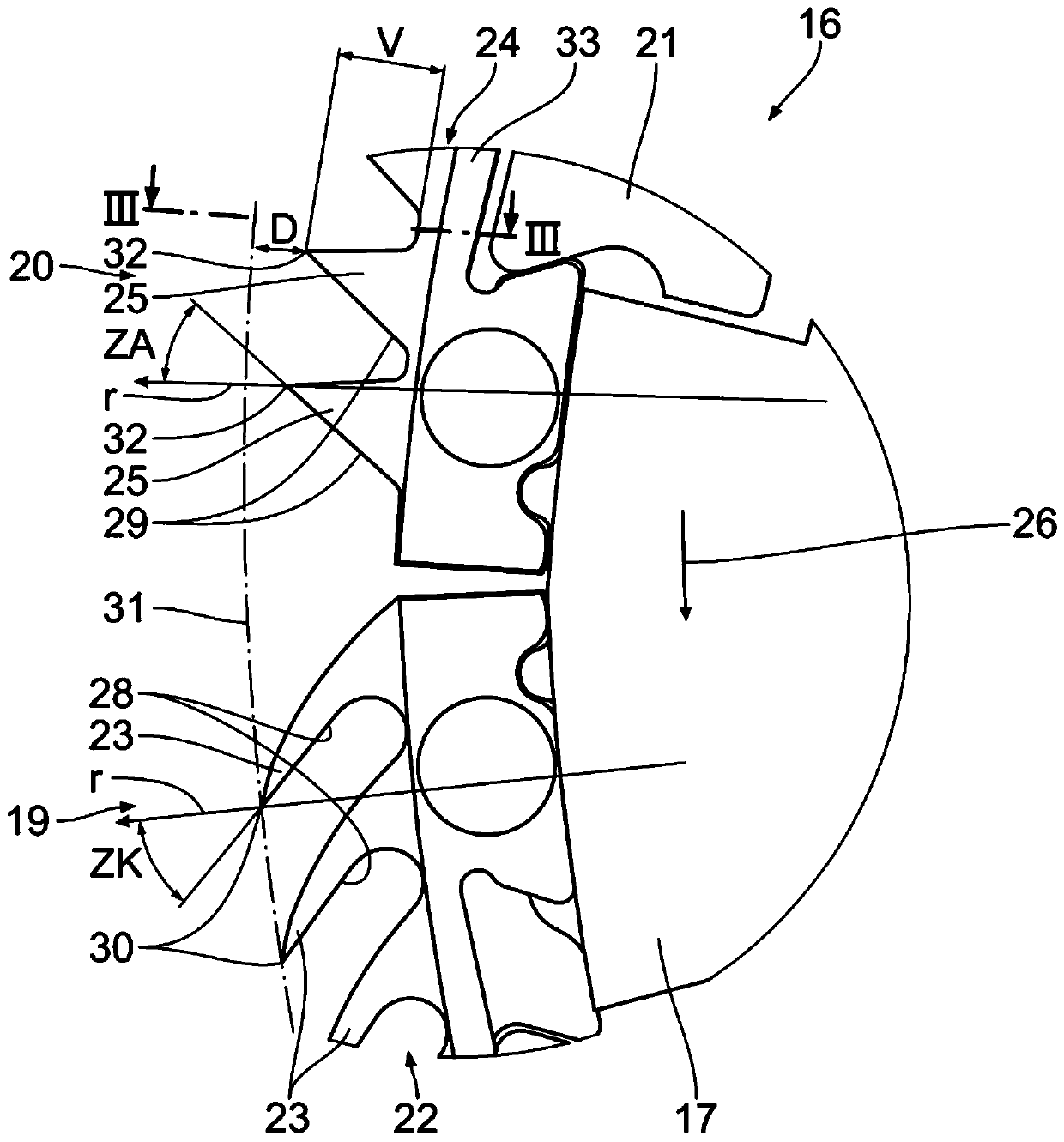
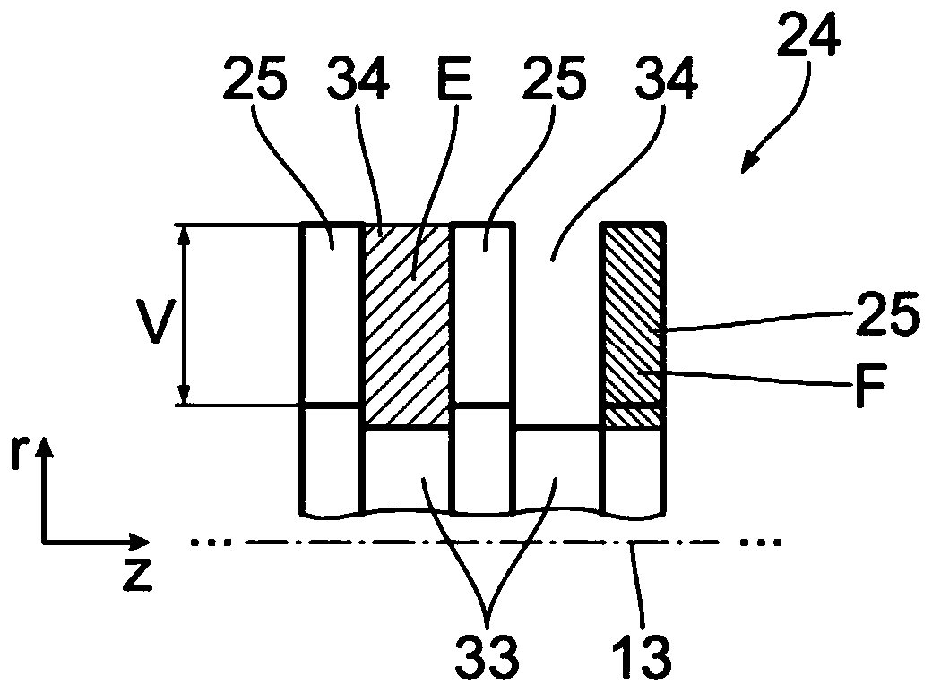
[0035] The corresponding parts are in Figures 1 to 7 Indicated with the same reference numerals. Details of the exemplary embodiments taken alone and explained in more detail hereinafter may also form part of the inventive or patentable subject matter.

[0036] figure 1 An exemplary embodiment of a carding machine 1 for carding textile fibers 2 is shown, said figure showing only some components of this carding machine 1 . Therein, the card has a nipper assembly 3 with an upper nipper 4 and a lower nipper 5 for feeding the textile fibers 2 to be carded. The upper nipper 4 and the lower nipper 5 can be opened and closed during the carding cycle (=nipping cycle). exist figure 1 , shows the open state. The nipper assembly also performs a relative movement with respect to the other machine components of the carding machine 1 , in particular with respect to the separating unit 6 comprising stationary traction rollers 7 , 8 , 9 and 10 . The pulling rollers 7 to 10 are arranged...


PUM


Abstract

Disclosed is a circular comb (16) serves for fastening to a shaft (14), which is rotatable about an axis of rotation (13) in a combing direction (26), of a comber (1) which is intended to comb textile fibers (2) and has fixed drawing-off rollers (7, 8, 9, 10) for the combed textile fibers (11). The circular comb (16) has, on a circular-comb main-body unit (17) having an outer side (18), a combing segment (19) having a plurality of combing bars (22) which are arranged on the outer side (18) of the circular-comb main-body unit (17) and are equipped with outwardly protruding combing teeth (23), the front combing-teeth flanks of which, as seen in the combing direction (26), are each inclined in the combing direction (26), and an aligning segment (20) which is arranged on the outer side (18) of the circular-comb main-body unit (17) and is equipped with a plurality of outwardly protruding aligning elements (25), the front aligning-element flanks of which, as seen in the combing direction (26), are each inclined counter to the combing direction (26), and some of which are arranged one after another as seen in the combing direction (26).

Description

[0001] This patent application claims priority from German patent application DE 10 2017 201 678.8, the content of which is hereby incorporated by reference. technical field [0002] The invention relates to a circular comb to be fastened to the shaft of a carding machine, said shaft being rotatable in the carding direction about an axis of rotation, said carding machine being intended for carding textile fibers and having a fixed traction roller. Background technique [0003] Combs, for example for carding machines and configured as circular combs or circular combs, are known from previous public use, wherein carding elements are arranged on a circular comb body in order to engage fiber tufts of textile fibers to be carded. A comb provided with combing elements along at least a part of its circumference is called a circular comb. Its effective combing area can be, for example, 78°, 90°, 111° or 137° of the circumference of the circular comb profile. The carding element ca...

Claims


Application Information

Patent Timeline
Patent Type & Authority Applications(China)
IPC IPC(8): D01G19/10
CPCD01G19/105
Inventor 弗雷德里希·海宁格尔
Owner STAEDTLER & UHL
Learn More