Diaphragm valve

一种隔膜阀、隔膜的技术,应用在隔膜阀、隔膜、阀细节等方向,能够解决半导体制造设备费增大、半导体制品制造成本恶化等问题,达到加工容易、流动容易稳定、加工作业性好的效果

Active Publication Date: 2019-09-03
KAISHI SCT CO LTD
View PDF13 Cites 0 Cited by
  • Summary
  • Abstract
  • Description
  • Claims
  • Application Information

AI Technical Summary

Problems solved by technology

This also brings about an increase in the cost of semiconductor manufacturing equipment, and there is a problem that the manufacturing cost of semiconductor products deteriorates.

Method used


Image

  • Diaphragm valve
  • Diaphragm valve
  • Diaphragm valve

Examples


Embodiment

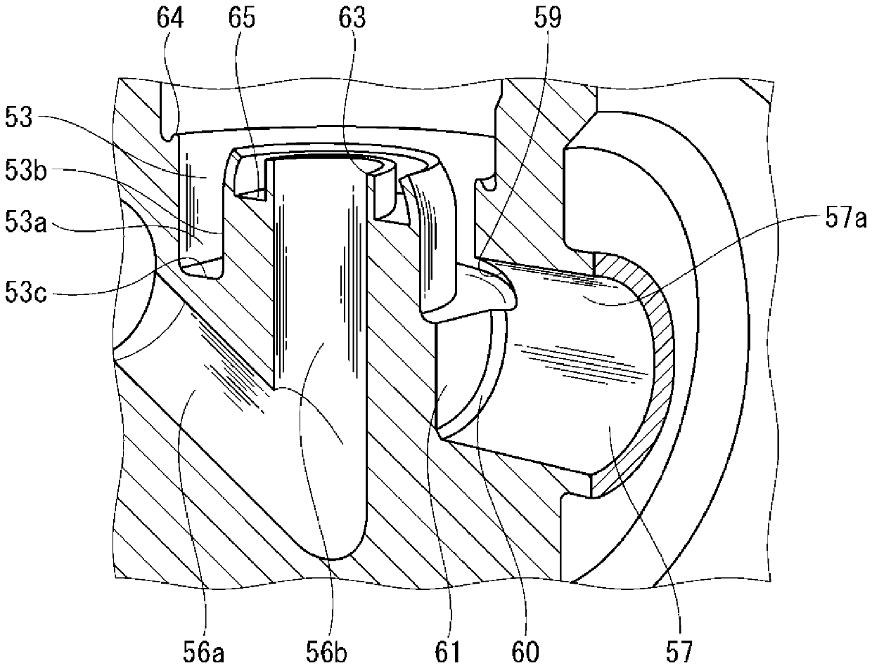
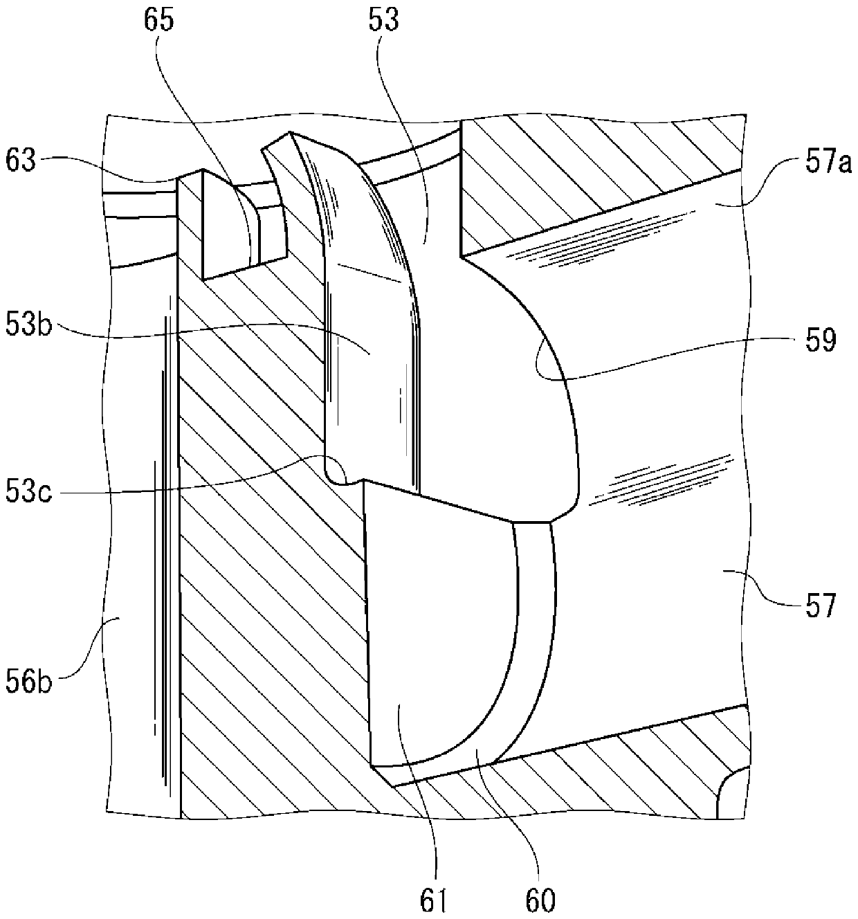
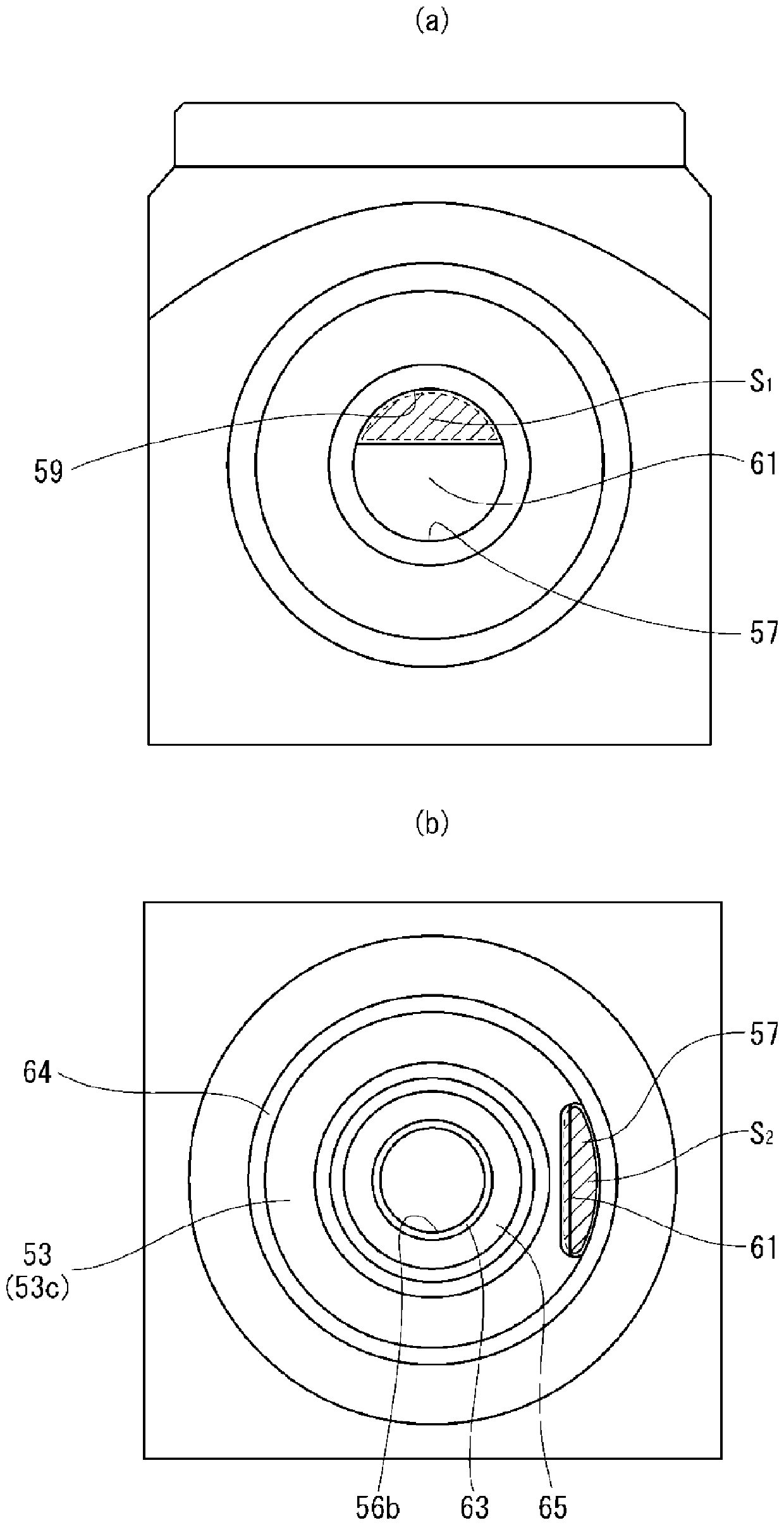
[0062] Next, fluid analysis of the diaphragm valve of this example will be described. In this fluid analysis, 0.75 was set as the target Cv value, and based on the analysis using a predetermined 3D-CAD fluid analysis software, the dimensions of each component of the flow path structure formed in the valve body 50 were found to satisfy this condition. the preferred range of values.

[0063] First of all, when discussing the size of the annular groove 53, it is obvious that a larger cross-sectional area can increase the Cv value of the valve. Therefore, if it is desired to increase the flow rate while avoiding an increase in the size of the valve, it is only necessary to make the annular groove 53 larger. It is sufficient to increase the cross-sectional area of ​​the shaped groove 53, but there are restrictions on the structure of the valve body 50. For example, it is not impossible to make the diameter of the outer surface 53a larger than the diameter of the convex portion 64 ...


PUM


Abstract

Provided is a diaphragm valve which is capable of exhibiting a high flow and a stable high Cv value, by enabling an optimal flow path space corresponding to a prescribed Cv value to be formed withoutcompromising body strength, even if a valve body is made very compact. This diaphragm valve is provided with: a valve seat (52) provided in a valve chamber inside a body (50); an annular groove (53) provided around the outer circumference of the valve seat (52); a diaphragm (55) provided so as to be capable of being brought into contact with and separated from the valve seat (52) via a pressing means; and a primary-side flow path (56) which communicates with the valve chamber (51). The inner diameter (R) of a secondary-side flow path (57) connected to the annular groove (53) is 2.0-4.5 times the groove width (W) of the annular groove (53). The cross-sectional area (S) of an intersection between the annular groove (53) and the secondary-side flow path (57) is smaller than the cross-sectional area (T) of the secondary-side flow path (57). The cross-sectional area (S) of the intersection is set so as to be at least 35% of the cross-sectional area (T) of the secondary-side flow path (57),to obtain a prescribed Cv value.

Description

technical field [0001] The present invention relates to a diaphragm valve, and particularly relates to a diaphragm valve capable of exhibiting a stable high flow rate (high Cv value) while being very compact and miniaturized, and suitable for use, for example, in a gas supply system to a semiconductor manufacturing device. Background technique [0002] In general, a so-called direct contact type diaphragm valve is mainly used as a control valve of a gas supply system in a semiconductor manufacturing process. The advantages of the direct diaphragm valve are as follows: Since the valve seat is directly closed by the metal diaphragm used as a seal against the outside, it can constitute a very simple flow path without redundant parts in the gas contact part, Therefore, there is no sliding part between metals in the gas contact part, and it becomes the most suitable structure for cleaning the fluid. However, there is a limit to the stroke that can be ensured, and it is difficult...

Claims


Application Information

Patent Timeline
Patent Type & Authority Applications(China)
IPC IPC(8): F16K7/16F16K7/17F16K27/02
CPCF16K7/17F16K27/0236F16K27/02F16K7/16H01L21/67017F16K31/52491
Inventor 高朝克图
Owner KAISHI SCT CO LTD
Why Eureka
Try Eureka