Light-emitting device

A technology of light-emitting devices and light-emitting chips, applied in electrical components, electric solid-state devices, circuits, etc., can solve the problems that the light and dark cutoff cannot be displayed clearly, obstruct the driver's vision, and light loss, etc., to prevent light leakage, prevent light loss, Addressing the effect of reduction

Pending Publication Date: 2019-09-17
SEOUL SEMICONDUCTOR
View PDF9 Cites 2 Cited by
  • Summary
  • Abstract
  • Description
  • Claims
  • Application Information

AI Technical Summary

Problems solved by technology

[0005] If light leakage occurs on the side of a light emitting device applied to an automotive lamp, the cut-off line, which is the boundary between bright and dark portions generated when the light emitted from the automotive lamp is irradiated forward, cannot be clearly displayed
As a result, there is a problem that the driver irradiates light to an unnecessary area, possibly obstructing the view of other drivers, and there is a problem that light loss occurs because the light is released from the side of the light emitting device.

Method used


Image

  • Light-emitting device
  • Light-emitting device
  • Light-emitting device

Examples


Embodiment Construction

[0031] Hereinafter, embodiments of the present invention will be described in detail with reference to the drawings. In order to fully convey the idea of ​​the present invention to those skilled in the art, the embodiments described below are provided as examples. Therefore, the present invention is not limited to the Examples described below, and may be embodied in other forms. In addition, in the drawings, the width, length, thickness, and the like of constituent elements may be exaggerated for convenience. Throughout the specification, the same reference symbols represent the same constituent elements, and similar reference symbols represent similar constituent elements.

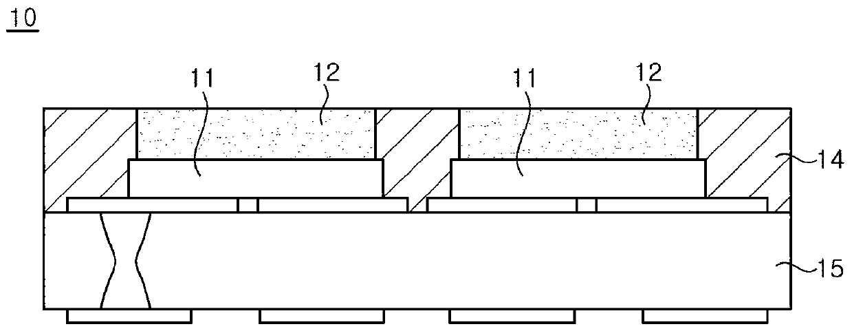
[0032] A light emitting device according to an embodiment of the present invention includes a substrate, a first light emitting chip, a first wavelength converting member, and a blocking member. The first light-emitting chip is mounted on the substrate. The first wavelength converting member covers the...


PUM


Abstract

The present invention relates to a light-emitting device. A light-emitting device according to one embodiment of the present invention comprises a substrate, a first light-emitting chip, a first wavelength conversion member, and a barrier member. The first light-emitting chip is mounted on the substrate. The first wavelength conversion member covers the upper surface of the first light-emitting chip. A first reflective member covers the side surface of the first wavelength conversion member. Further, the barrier member comprises an outer wall portion surrounding the side surfaces of the first light-emitting chip and the first reflective member.

Description

technical field [0001] The invention relates to a light emitting device. Background technique [0002] A light-emitting chip is a semiconductor element that emits light generated by recombination of electrons and holes, and recently, the light-emitting chip is utilized in various fields such as displays, automotive lamps, general lighting, and the like. Light-emitting chips have a long life, low power consumption, and fast response, so they are being used in various fields such as automotive lighting and display devices. [0003] figure 1 It is a cross-sectional view showing a conventional light-emitting device. refer to figure 1 , the existing light-emitting device 10 includes a light-emitting chip 11 , a wavelength conversion member 12 , a blocking member 14 and a circuit substrate 15 . The barrier member 14 is formed of a material containing a reflective substance in resin. Therefore, the blocking member 14 functions to reflect the light released from the light emitt...

Claims


Application Information

Patent Timeline
Patent Type & Authority Applications(China)
IPC IPC(8): H01L33/50H01L33/60H01L33/62
CPCH01L33/60H01L33/54H01L25/0753H01L33/50H01L33/62H01L33/504H01L33/502H01L33/20H01L25/167
Inventor 金譿认孙正勳
Owner SEOUL SEMICONDUCTOR
Why Eureka
Try Eureka