A sliding suction cup with an elastic sheath
A sliding type and sliding disc technology, which is applied in the direction of window cleaning, carpet cleaning, cleaning devices, etc., can solve the problems of adsorption failure, adsorption vacuum degree reduction, curtain wall cleaning robot can not continue to work, etc., to restore adsorption and improve service life , the effect of simple structure
- Summary
- Abstract
- Description
- Claims
- Application Information
AI Technical Summary
Problems solved by technology
Method used
Image
Examples
Embodiment 1
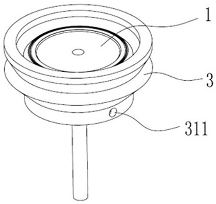
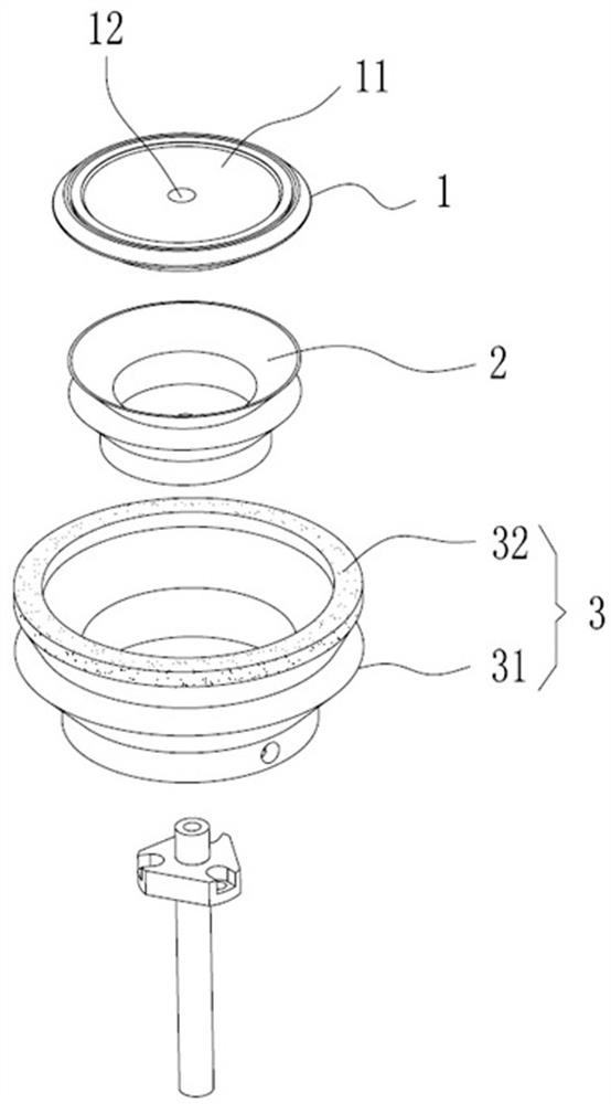
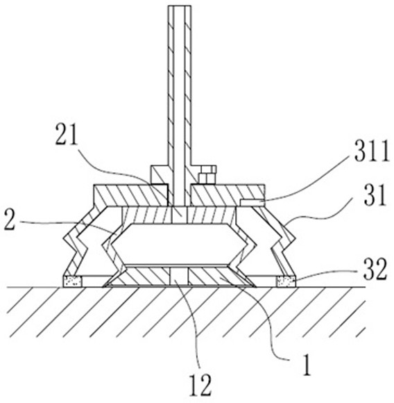
[0030] like figure 1 , figure 2 As shown, this embodiment discloses a sliding suction cup with an elastic sheath, including a sliding disc 1, an elastic cup 2, an elastic sheath 3 and a vacuum generator (not shown). A groove 11 is formed inwardly on the surface of the sliding plate 1 that fits with the adsorption plane, and an air suction hole 12 communicating with the elastic cup 2 is arranged in the groove 11 . One end of the elastic leather cup 2 is connected with the sliding plate 1, and the other end is provided with a second air extraction hole 21.
[0031] The elastic sheath 3 is set on the periphery of the elastic cup 2. The elastic sheath 3 includes a sheath cup 31 and a contact ring 32. The contact ring 32 is in sealing connection with the sheath cup 31. The contact ring 32 is attached to the adsorption plane, and the adsorption plane The bonding surface is the open end, and the surface of the open end protrudes beyond the surface of the sliding plate 1 by a dista...
Embodiment 2
[0035] like Figure 5 , Figure 6 As shown, this embodiment discloses a sliding suction cup with an elastic sheath, including a sliding disk 1, an elastic cup 2, an elastic sheath 3, a vacuum generator, a connecting rod 4, a back pressure suction cup 5, an elastic reset assembly 6, Sealing cover 7 and fixing frame 8. In this embodiment, the elastic return assembly 6 includes a fixed plate 61 , a telescopic slider 62 , four guide rods 63 and four sets of springs 64 . like Figure 7 As shown, the connecting rod 4 in this embodiment is a hollow structure to communicate with the elastic cup 2 and the back pressure suction cup 5 .
[0036] A groove 11 is formed inwardly on the surface of the sliding plate 1 that fits with the adsorption plane, and an air suction hole 12 communicating with the elastic cup 2 is arranged in the groove 11 . One end of the elastic leather cup 2 is connected with the sliding plate 1, and the other end is provided with a second air extraction hole 21....
Embodiment 3
[0040] like Figure 8 , Figure 9 As shown, the difference between the present embodiment and the second embodiment is that the elastic return assembly 6 in the present embodiment includes a spring 64 and a bushing 65 . In this embodiment, the middle part of the connecting rod 4 is a solid structure, and the two ends of the connecting rod 4 are split hollow structures. The hollow structures at both ends of the connecting rod 4 are connected with joints 42, and the two joints 42 are connected through the air pipe. A first gas path valve 91 is set between the back pressure suction cup 5 and the vacuum generator, a second gas path valve 92 is set between the second pumping hole 21 and the vacuum generator, and a second gas path valve 92 is set between the third pumping hole 311 and the vacuum generator. There is a third gas path valve 93. The connecting rod 4 is set as a solid structure in the middle. Compared with the second embodiment, the strength is higher, so that the conn...
PUM
 Abstract
Description
Claims
Application Information
 - R&D
- Intellectual Property
- Life Sciences
- Materials
- Tech Scout
- Unparalleled Data Quality
- Higher Quality Content
- 60% Fewer Hallucinations
Browse by: Latest US Patents, China's latest patents, Technical Efficacy Thesaurus, Application Domain, Technology Topic, Popular Technical Reports.
© 2025 PatSnap. All rights reserved.Legal|Privacy policy|Modern Slavery Act Transparency Statement|Sitemap|About US| Contact US: help@patsnap.com


