Eureka AIR delivers breakthrough ideas for toughest innovation challenges, trusted by R&D personnel around the world.

Glue cylinder and glue feeding method thereof

A glue tank and glue feeding technology, applied in special distribution devices, packaging, distribution devices, etc., can solve problems such as corrosion, harsh working environment, false alarms, etc., and achieve the effects of easy maintenance, prevention of cylinder explosion, and high reliability

Pending Publication Date: 2019-09-20
GUANGDONG TRANSHELL PACKAGING
View PDF0 Cites 0 Cited by
  • Summary
  • Abstract
  • Description
  • Claims
  • Application Information

AI Technical Summary

Problems solved by technology

[0002] In the glue tank of the glue injection machine in the prior art, field sensors are generally installed in the glue tank to control the amount of glue fed into the glue tank, and multiple liquid level sensors of different heights are also installed in the glue tank, both It can ensure sufficient glue storage in the glue tank and prevent the glue tank from exploding due to the excessive amount of glue in the glue tank. The liquid level sensor is corroded, which makes the liquid level sensor abnormally misreport the liquid level in the cylinder, causing the glue tank to explode; and the liquid level sensor works with a spot, and under the combined action of ammonia water, the glue at the liquid level probe is easy to condense. Granular foreign matter will affect the injection quality of the subsequent injection machine

Method used


Image

  • Glue cylinder and glue feeding method thereof
  • Glue cylinder and glue feeding method thereof
  • Glue cylinder and glue feeding method thereof

Examples


Embodiment Construction

[0024] A glue injection device and a glue feeding method of the present invention are described in conjunction with the accompanying drawings.

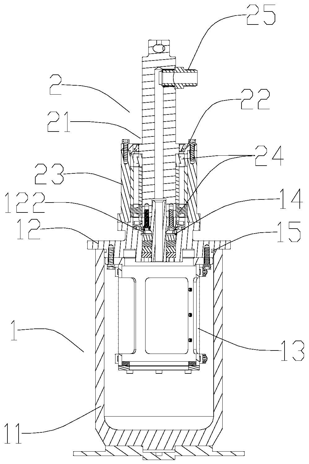
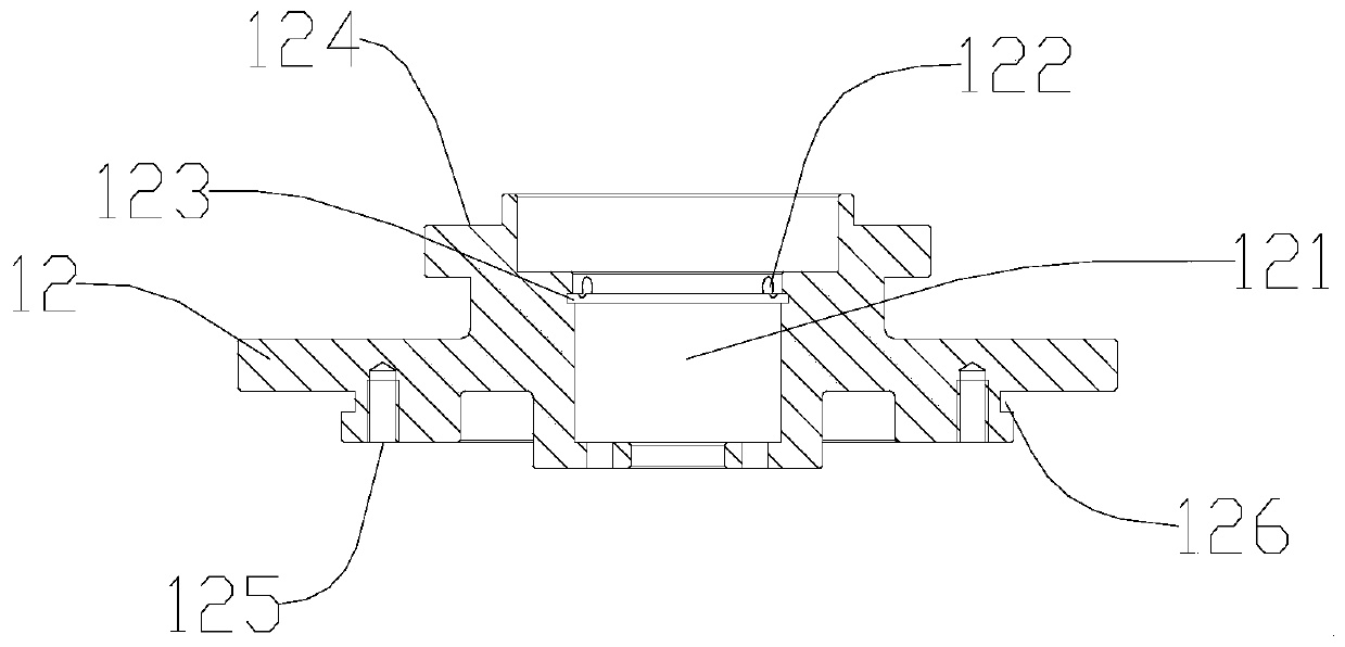
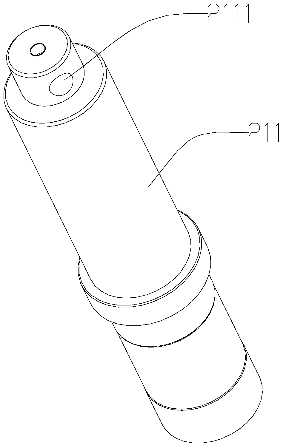
[0025] Such as Figures 1 to 5 A glue tank shown (where part of the glue feed channel is not shown, including the part of the back pressure valve and the pressure regulating valve), includes a glue tank and a glue feed channel for feeding glue into the cylinder body 1, wherein the cylinder body 1 includes The main body 11 and the cover body 12 are fixedly connected. The middle part of the cover body 12 is provided with an opening 121. The opening 121 is used for inserting the glue feeding channel into the main body 11 to feed glue. According to the cylinder body 1 The use environment requires long-term storage of glue, and for the corrosive ammonia water contained in the water-based glue, the cylinder body 1 needs to be made of a suitable corrosion-resistant material. It is preferable that the cylinder body 1 is made of ammonia-water ...


PUM


Abstract

The invention relates to a glue cylinder comprising a cylinder block of the glue cylinder and a glue feeding passage for feeding glue into the cylinder block. The glue feeding passage comprises a pressure regulating valve and a back pressure valve, the pressure regulating valve is arranged at the front end of the glue feeding passage, the back pressure valve is arranged at the rear end of the pressure regulating valve, the pressure regulating valve has a first pressure threshold value, and pressure relief is carried out at the pressure regulating valve when the pressure of the glue in the glue feeding passage is larger than the first pressure threshold value; the back pressure valve has a second pressure threshold value, and the back pressure valve is opened when the pressure of the glue in the glue feeding passage is greater than the second pressure threshold value; the cylinder block comprises a body and a cover body, the middle portion of the cover body is provided with an opening, the opening allows the glue feeding passage to be inserted into the body for glue feeding, a first sealing ring is arranged between the glue feeding passage and the hole, and a glue leaking observing hole is formed in the position corresponding to the first sealing ring and on the side wall, provided with the hole, of the cover body. The invention also provides a glue feeding method of the glue cylinder. According to a new glue cylinder glue feeding control structure and the glue feeding control method, a liquid level sensor in a traditional glue cylinder is eliminated, and influences of the liquid level sensor on the quality of the glue in the glue cylinder are avoided.

Description

technical field [0001] The invention relates to the field of glue injection devices, in particular to a glue tank and a glue feeding method thereof. Background technique [0002] In the glue tank of the glue injection machine in the prior art, field sensors are generally installed in the glue tank to control the amount of glue fed into the glue tank, and multiple liquid level sensors of different heights are also installed in the glue tank, both It can ensure sufficient glue storage in the glue tank and prevent the glue tank from exploding due to the excessive amount of glue in the glue tank. The liquid level sensor is corroded, which makes the liquid level sensor abnormally misreport the liquid level in the cylinder, causing the glue tank to explode; and the liquid level sensor works with a spot, and under the combined action of ammonia water, the glue at the liquid level probe is easy to condense. Granular foreign matter will affect the injection quality of the subsequent...

Claims


Application Information

Patent Timeline
Patent Type & Authority Applications(China)
IPC IPC(8): B67D7/78B67D7/42B67D7/36
CPCB67D7/78B67D7/42B67D7/36
Inventor 王康余帮贵
Owner GUANGDONG TRANSHELL PACKAGING
Why Eureka
Eureka Blog
Learn More