Automatic supply and discharge system and purification device for medical liquid reagent

A purification device and automatic technology, applied in the field of medical devices, can solve the problems of incapable of harmless and timely recycling and disposal of medical reagents, heavy workload of medical staff, inability to remove odors of chemical reagents, etc. The effect of timely process and safe operation

Active Publication Date: 2019-09-20
孝感市爱普丽生电子科技有限公司
View PDF30 Cites 1 Cited by
  • Summary
  • Abstract
  • Description
  • Claims
  • Application Information

AI Technical Summary

Problems solved by technology

[0003] The purpose of the present invention is to solve the working mode in which medical staff supply medical reagents by hand in the prior art, manual control and foot control cannot be used to control the supply and discharge flow of reagents, the workload of medical staff is heavy, and biological specimens cannot be preserved in time , can not harmlessly recover and process related medical reagents in time, can not remove the shortcomings of chemical reagent odor in the process of pathological tissue sampling, and proposes an automatic supply and discharge system and purification device for medical liquid reagents

Method used


Image

  • Automatic supply and discharge system and purification device for medical liquid reagent
  • Automatic supply and discharge system and purification device for medical liquid reagent
  • Automatic supply and discharge system and purification device for medical liquid reagent

Examples


Embodiment Construction

[0022] The following will clearly and completely describe the technical solutions in the embodiments of the present invention with reference to the accompanying drawings in the embodiments of the present invention. Obviously, the described embodiments are only some, not all, embodiments of the present invention.

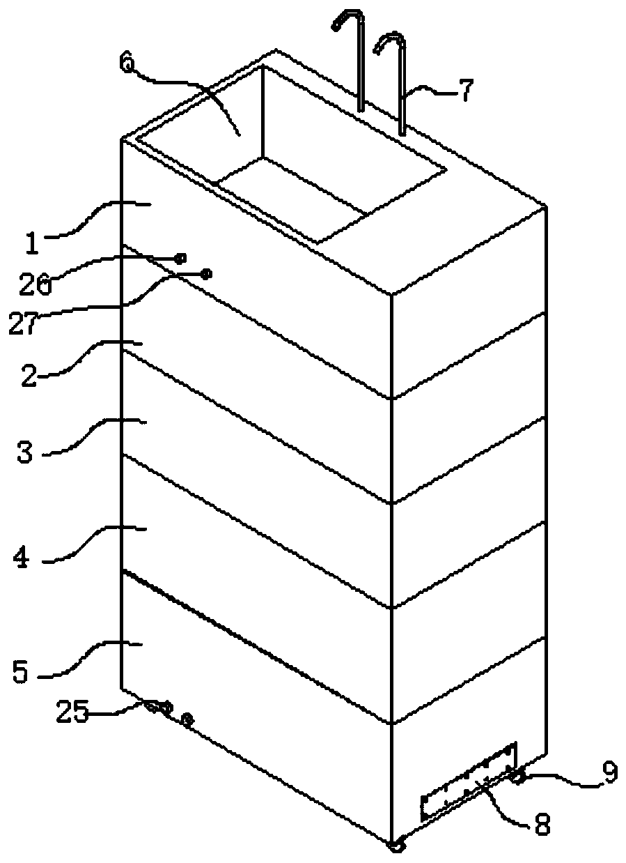
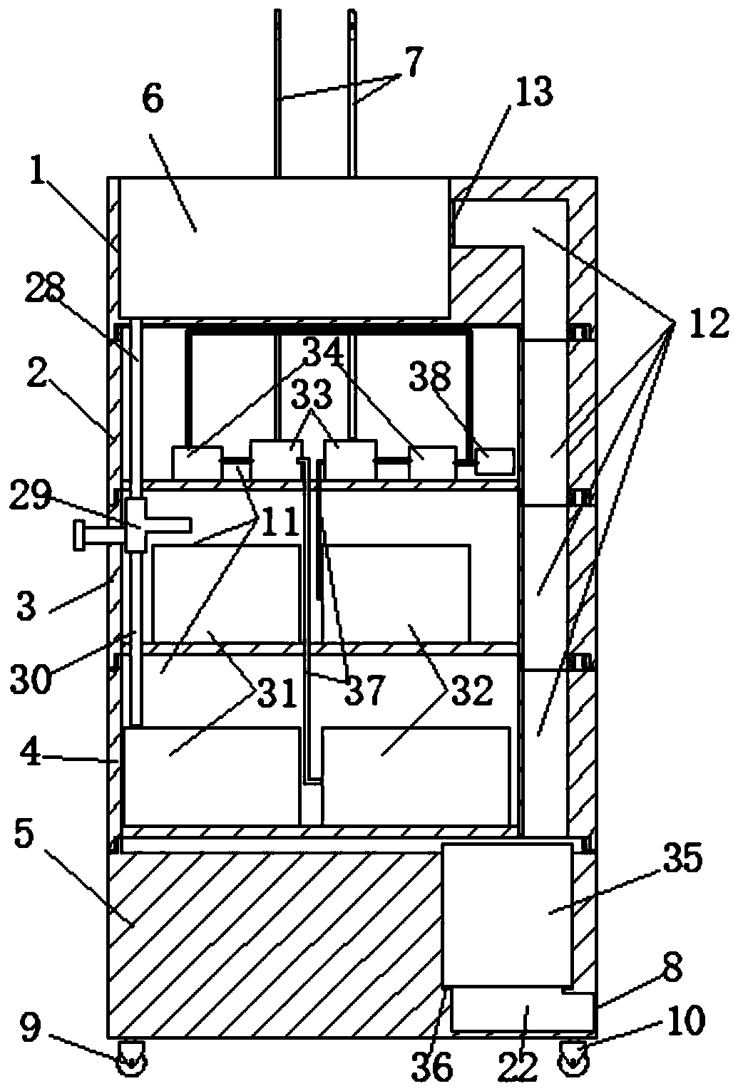
[0023] refer to Figure 1-5 , an automatic supply and discharge system and purification device for medical liquid reagents, including a base block 5, a placement groove 36 is opened on one side of the top of the base block 5, an air outlet channel 22 is opened on the side of the base block 5, and the air outlet channel 22 and the placement slot 36 is connected, and a gas purification mechanism 35 is placed in the placement tank 36.

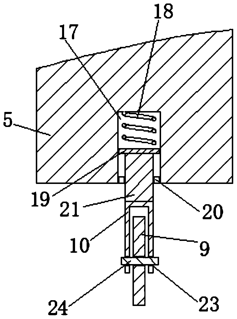
[0024] The bottom end of the base block 5 is equipped with a rolling mechanism. The rolling mechanism includes four roller holes 17. The four roller holes 17 are respectively located at the four corners of the bottom end of the base bloc...


PUM


Abstract

The invention relates to the technical field of medical devices and in particular relates to an automatic supply and discharge system and purification device for a medical liquid reagent. The automatic supply and discharge system and purification device comprises a base block; a placing groove is formed in one side of the top end of the base block; an air outlet channel is formed in the side of the base block; a fourth block body is placed on the top end of the base block; a third block body is placed on the top end of the fourth block body; a second block body is placed on the top end of the third block body; a first block body is placed on the top end of the second block body; a waste liquid recovery pool is formed in one side of the top end of the first block body; a sealing ring is adhered to a position, relative to an air suction channel, at the bottom end of the first block body; storage grooves are formed in top ends of the first block body, the second block body, the third block body and the fourth block body; a liquid delivery working pump is placed in the storage groove of the second block body; the input end of the liquid delivery working pump communicates with a liquid inlet pipe, and the other end of the liquid inlet pipe is inserted into a liquid delivery vessel; the bottom end of the waste liquid recovery pool communicates with a first waste liquid recovery pipe; the outside of the waste liquid working pump is connected with a control mechanism; and the output end of the liquid delivery working pump communicates with a liquid feeding pipe. The automatic supply and discharge system and purification device is simple in structure and worthy of popularization.

Description

technical field [0001] The invention relates to the technical field of medical devices, in particular to an automatic supply and discharge system and purification device for medical liquid reagents. Background technique [0002] The automatic supply and discharge system and purification device for medical liquid reagents are mainly used in the operation process of pathological instruments in the industry to self-supply and discharge the chemical reagents used in related supporting facilities, and to purify the generated odor gases and odors generated by biological tissues. Realize no odor discharge, achieve pollution-free emission reduction and environmental protection effect. In the existing technology, the most similar use in the manufacturing field of this industry is manual feeding of reagents into specimen containers, which cannot realize the automatic supply and harmlessness of medical reagents. At the same time, the peculiar smell in the air is not absorbed and filter...

Claims


Application Information

Patent Timeline
Patent Type & Authority Applications(China)
IPC IPC(8): C02F1/00B01D46/12
CPCC02F1/008B01D46/12
Inventor 肖华圣
Owner 孝感市爱普丽生电子科技有限公司
Why Eureka
Try Eureka