Home decoration scaffold
A technology for scaffolding and home decoration, which is applied to the accessories of scaffolding, building structure support, building structure support, etc. It can solve the problem of single function of integrated scaffolding, and achieve the effect of convenient toolbox, high practical value, and convenient disassembly and assembly
- Summary
- Abstract
- Description
- Claims
- Application Information
AI Technical Summary
Problems solved by technology
Method used
Image
Examples
Embodiment 1
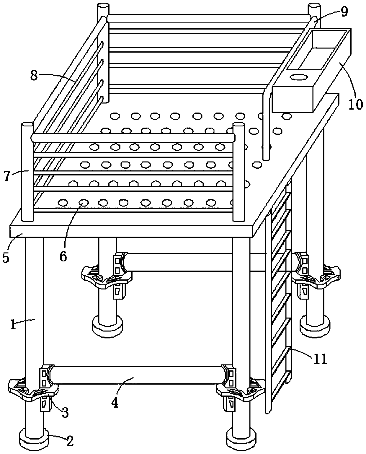
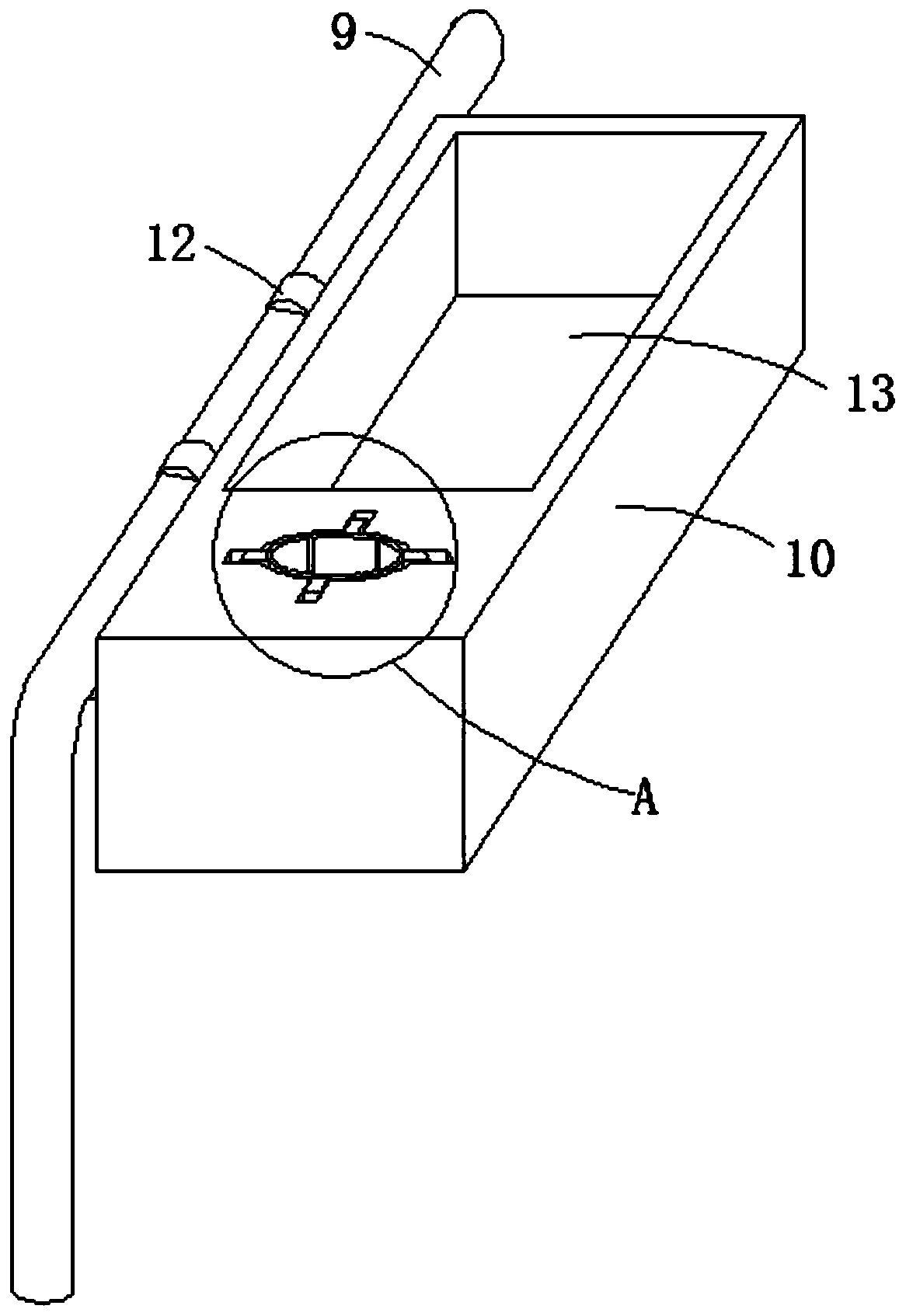
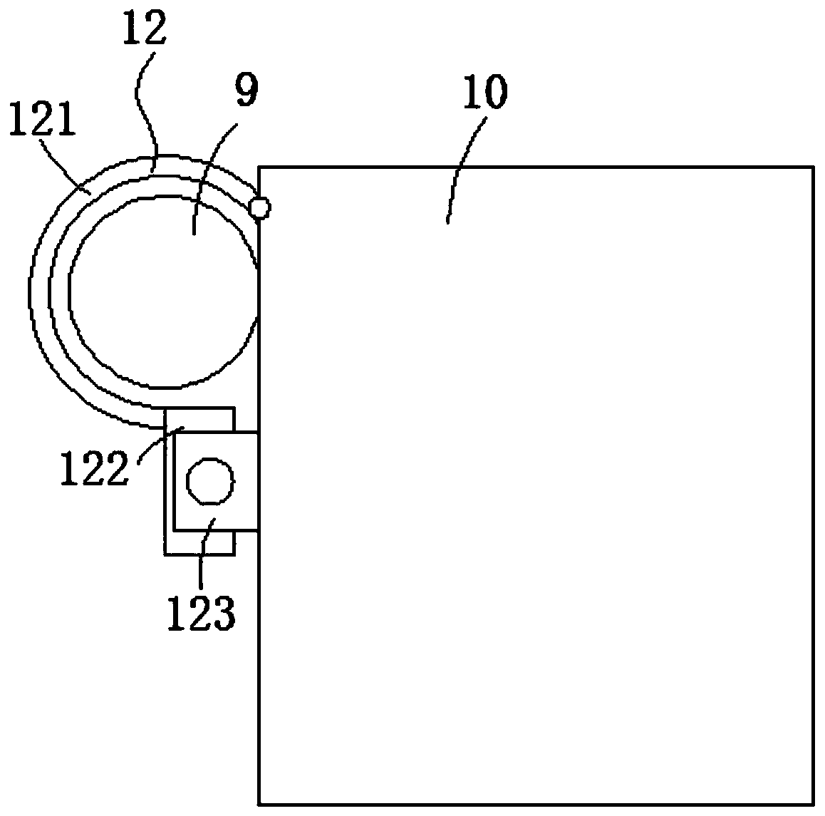
[0035] Such as figure 1 , 2 As shown in and 3, a home improvement scaffolding is proposed in this embodiment, including a vertical column 1, a base 2, a connecting piece 3, a horizontal column 4 and a pedal 5, and the vertical column 1 and the horizontal column 4 are connected through the connecting piece 3. connection, the base 2 is arranged on the lower end surface of the vertical column 1, the foot pedal 5 is arranged on the upper end surface of the vertical column 1, the foot pedal 5 is arranged as a rectangular structure, and the foot pedal 5 is provided with an anti-slip protrusion 6, and The upper plate surface of pedal 5 is provided with three sides protective fence 7, and one side upper end of pedal 5 is not provided with fence is fixedly provided with installation rod 9, and the free end of installation rod 9 is fixedly arranged on three sides protection fence 7, and foot A climbing ladder 11 is provided at the lower end of the side of the pedal 5 that is not provid...
Embodiment 2
[0042] Such as Figure 4 As shown, the difference between embodiment 2 and embodiment 1 is that in embodiment 2, in order to achieve a better fixing effect between the installation rod 9 and the tool box 10, a snap-in groove 124, a snap-in rod 125 and a snap-in connection are added. The combined structure of the spring 126, during the installation process, the fixing plate 122 enters the fixing groove 123, which will cause the clamping rod 125 to enter into the clamping groove 124, thereby limiting the fixing plate 122 and the fixing groove 123. To achieve the fixing effect, when disassembling, pull the clamping rod 125 out of the clamping groove 124, so that the fixing plate 122 and the fixing groove 123 have relative movement capability.
[0043] Preferably, one end of the clamping rod 125 outside the clamping groove 124 is provided with a drawing plate 127 , so that when the clamping rod 125 is pulled, a more convenient operation can be achieved.
Embodiment 3
[0045] Such as Figure 5 and Figure 6 As shown, the difference between embodiment 3 and embodiments 1 and 2 is that in embodiment 3, a bottle placement hole 14 is provided on the tool box 10, so that it can be used for conveniently placing a water cup, and is convenient for storing water after a long time of work. Supplement, at the same time, a combined structure of clamping circular arc plate 15, moving slider 16, moving chute 17 and supporting spring 18 is added in the bottle body placement hole 14. The setting of this combined structure is used to clamp the water cup. This can prevent the water cup from shaking in the bottle body placement hole 14, thereby playing a role in fixing the water cup. At the same time, by fixing the water cup, it can also avoid damage to the water cup.
[0046] Preferably, in this embodiment, the side of the clamping arc plate 15 facing the bottle placement hole 14 is fixedly provided with a sponge pad 19, the sponge pad 19 has a certain thick...
PUM
 Abstract
Description
Claims
Application Information
 - R&D Engineer
- R&D Manager
- IP Professional
- Industry Leading Data Capabilities
- Powerful AI technology
- Patent DNA Extraction
Browse by: Latest US Patents, China's latest patents, Technical Efficacy Thesaurus, Application Domain, Technology Topic, Popular Technical Reports.
© 2024 PatSnap. All rights reserved.Legal|Privacy policy|Modern Slavery Act Transparency Statement|Sitemap|About US| Contact US: help@patsnap.com


