Performance testing device for variable thrust rocket engine or thrust chamber of engine

A rocket engine and test device technology, which is applied to rocket engine devices, jet propulsion devices, machines/engines, etc., and can solve problems such as the inability to perform fluid flow performance tests with back pressure

Active Publication Date: 2019-09-20
XIAN AEROSPACE PROPULSION INST
View PDF5 Cites 5 Cited by
  • Summary
  • Abstract
  • Description
  • Claims
  • Application Information

AI Technical Summary

Problems solved by technology

[0006] In order to solve the technical problem that the existing rocket engine thrust chamber performance test device cannot perform the liquid flow performance test with back pressure, the present invention provides a variable thrust rocket engine or engine thrust chamber performance test device

Method used


Image

  • Performance testing device for variable thrust rocket engine or thrust chamber of engine
  • Performance testing device for variable thrust rocket engine or thrust chamber of engine
  • Performance testing device for variable thrust rocket engine or thrust chamber of engine

Examples


Embodiment 1

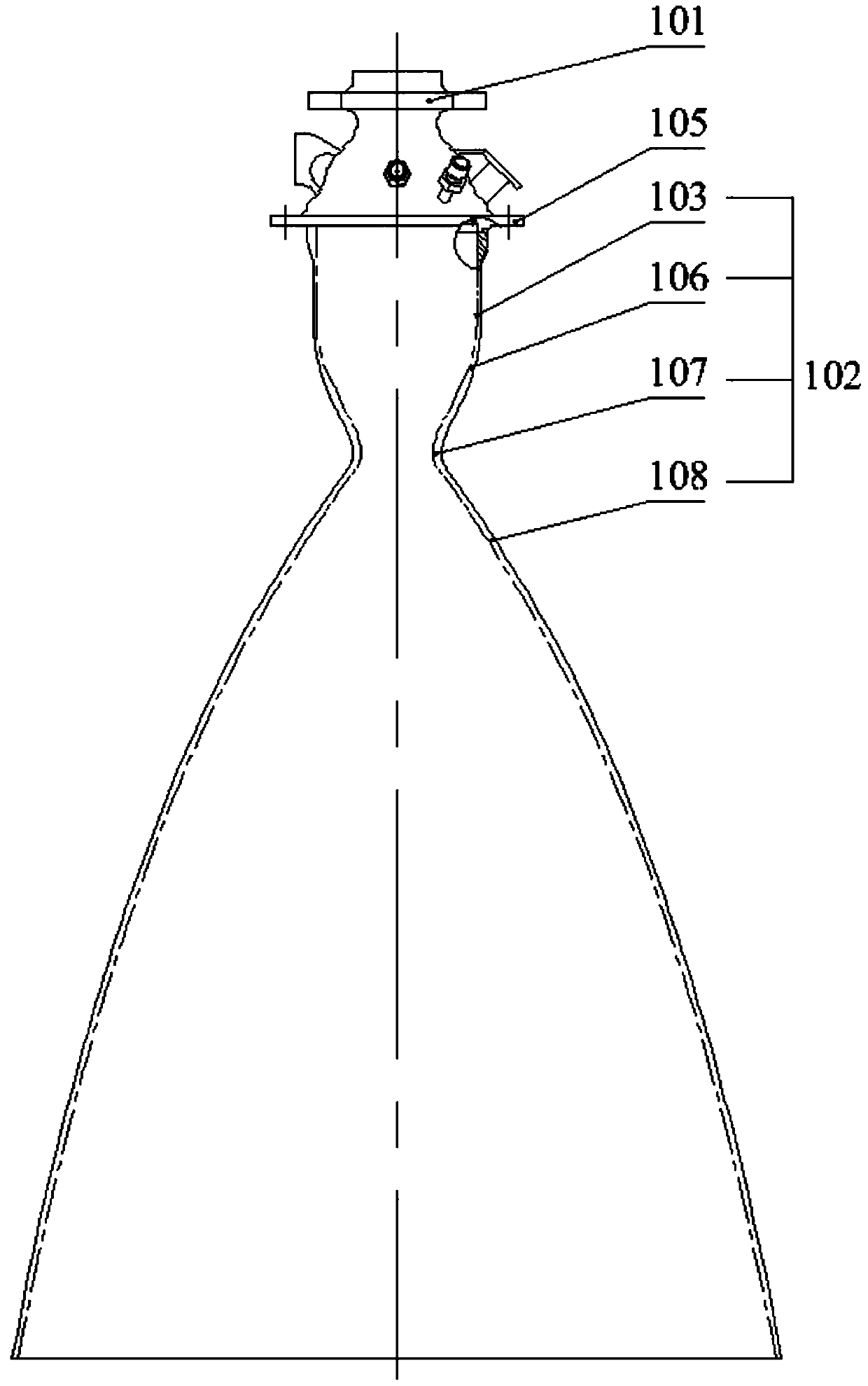
[0052] Embodiment 1, this embodiment is suitable for testing the engine thrust chamber of the short nozzle state of the variable thrust rocket engine.

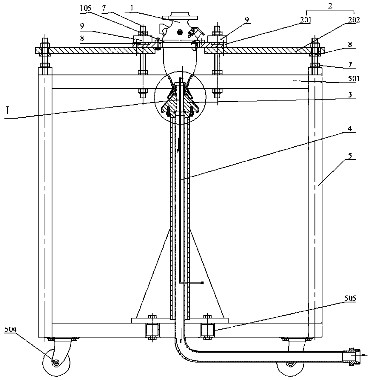
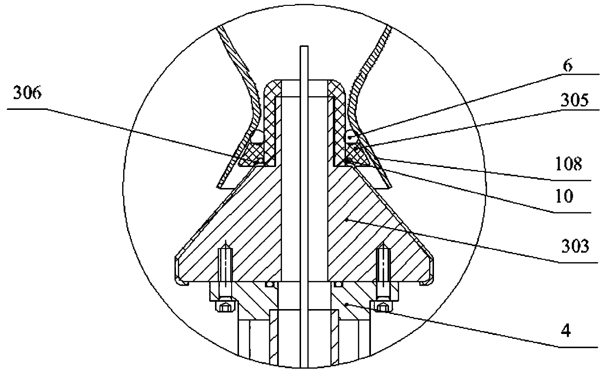
[0053] refer to figure 2 and image 3 , the variable thrust rocket engine or engine thrust chamber performance testing device includes an anti-roof assembly 2, a throat support assembly 3, a bottom support assembly 4, a bench 5 and a strip-shaped pressure plate 9.

[0054] refer to Figure 8 to Figure 10 , the stand 5 includes an upper frame 521 , a lower frame 522 and four columns 502 supported between the upper frame 521 and the lower frame 522 . The four sides of the stand 5 are provided with transparent plexiglass plates 509 to prevent water from splashing during the test and to facilitate observation of the test conditions. The transparent plexiglass plate 509 is inserted in the thin strip 513 with a bottom surface spot-welded on the outside of the column 502 . The bottom of the lower frame 522 is provided with four ...

Embodiment 2

[0064] Embodiment 2, this embodiment is suitable for testing the engine thrust chamber of the variable thrust rocket engine with tail nozzle state.

[0065] refer to Figure 11 , the difference between this embodiment and embodiment 1 is only:

[0066] In this embodiment, the height of the support ring 305 is higher. In order to raise the engine thrust chamber 1 and prevent the engine thrust chamber tail nozzle inner wall from contacting the throat support assembly 3 and scratching and scratching the engine thrust chamber, the support ring 305 The upper part is a cylinder 307, the lower part is a circular platform, and the upper end surface forms a sealing ring positioning groove, and two first sealing members 6 and third sealing members 11 of different sizes are placed. The engine thrust chamber 1 can achieve sealing when it contacts any sealing ring. As a result, setting two sealing rings has an axial positioning effect on the product and prevents the product from swinging ...

Embodiment 3

[0067] Embodiment 3, this embodiment is suitable for testing the small-sized throat engine thrust chamber of the variable thrust rocket engine.

[0068] refer to Figure 12 , the difference between this embodiment and embodiment 1 is only:

[0069] In this embodiment, the height of the support ring 305 is higher, and the upper end surface of the support ring 305 is provided with a slightly smaller first sealing ring 6 to adapt to the sealing size of the inner wall of the thrust chamber of the engine to achieve a sealing effect.


PUM


Abstract

The invention relates to a performance testing device of a rocket engine, in particular to a performance testing device for a variable thrust rocket engine or a thrust chamber of an engine, and solves the technical problem that an existing performance testing device for the thrust chamber of the engine cannot conduct a liquid flow performance test with a back pressure. The performance testing device for the variable thrust rocket engine or the thrust chamber of the engine is characterized by comprising an anti-ejection assembly, a throat supporting assembly, a bottom supporting assembly, a rack and a strip-type pressing plate. The rack comprises an upper frame, a lower frame and a column supported between the upper frame and the lower frame. The anti-ejection assembly connects a detected thrust chamber of the engine to the upper frame; the strip-type pressing plate is connected to the upper frame and the detected thrust chamber of the engine is compressed to the upper frame; the throat supporting assembly is supported on the engine or an expansion section of the thrust chamber of the engine; a bottom supporting assembly is arranged at the bottom of the throat supporting assembly; and the bottom supporting assembly is fixedly connected to the lower frame.

Description

technical field [0001] The invention relates to a performance testing device of a rocket engine, in particular to a performance testing device of a variable thrust rocket engine or a thrust chamber of the engine. Background technique [0002] In the development process of the variable thrust rocket engine, a number of liquid tests are required to obtain its performance parameters and verify whether the product design meets the technical requirements. Among them, the hydraulic test of the engine thrust chamber requires pressure drop matching debugging, stability test and back pressure test. [0003] refer to figure 1 , The engine thrust chamber 1 includes an injector 101 and a body 102 connected in series from top to bottom. The lower part of the injector 101 is provided with a connecting flange 105 . [0004] The body 102 includes a body cylindrical section 103, a convergent section 106 (above the throat), a throat 107 (where the diameter of the body is smallest), and a d...

Claims


Application Information

Patent Timeline
Patent Type & Authority Applications(China)
IPC IPC(8): F02K9/96
CPCF02K9/96
Inventor 徐亚丽
Owner XIAN AEROSPACE PROPULSION INST
Why Eureka
Try Eureka