a centrifugal fan

A centrifugal fan and air outlet technology, which is used in mechanical equipment, machines/engines, liquid fuel engines, etc., can solve the problems such as the decrease of the air speed of the air inlet of the range hood, the decrease of the sound quality of the range hood, and the disturbance of the volute airflow. Eliminate flow dead zone, improve fan performance and reduce airflow turbulence

Active Publication Date: 2021-01-19
NINGBO FOTILE KITCHEN WARE CO LTD
View PDF6 Cites 0 Cited by
  • Summary
  • Abstract
  • Description
  • Claims
  • Application Information

AI Technical Summary

Problems solved by technology

To sum up the above two factors, during the operation of the fan, due to the unfavorable factors of the circulating air flow and the vortex in the volute, the air flow in the volute will be disturbed, resulting in the loss of fan kinetic energy and the decrease of the wind speed. The oil fume escapes, which affects the decline of customer experience; secondly, the change of the flow field inside the fan is closely related to the generation of noise. Therefore, the vortex inside the volute will increase the noise and cause the sound quality of the range hood to decline

Method used


Image

  • a centrifugal fan
  • a centrifugal fan
  • a centrifugal fan

Examples


Embodiment 1

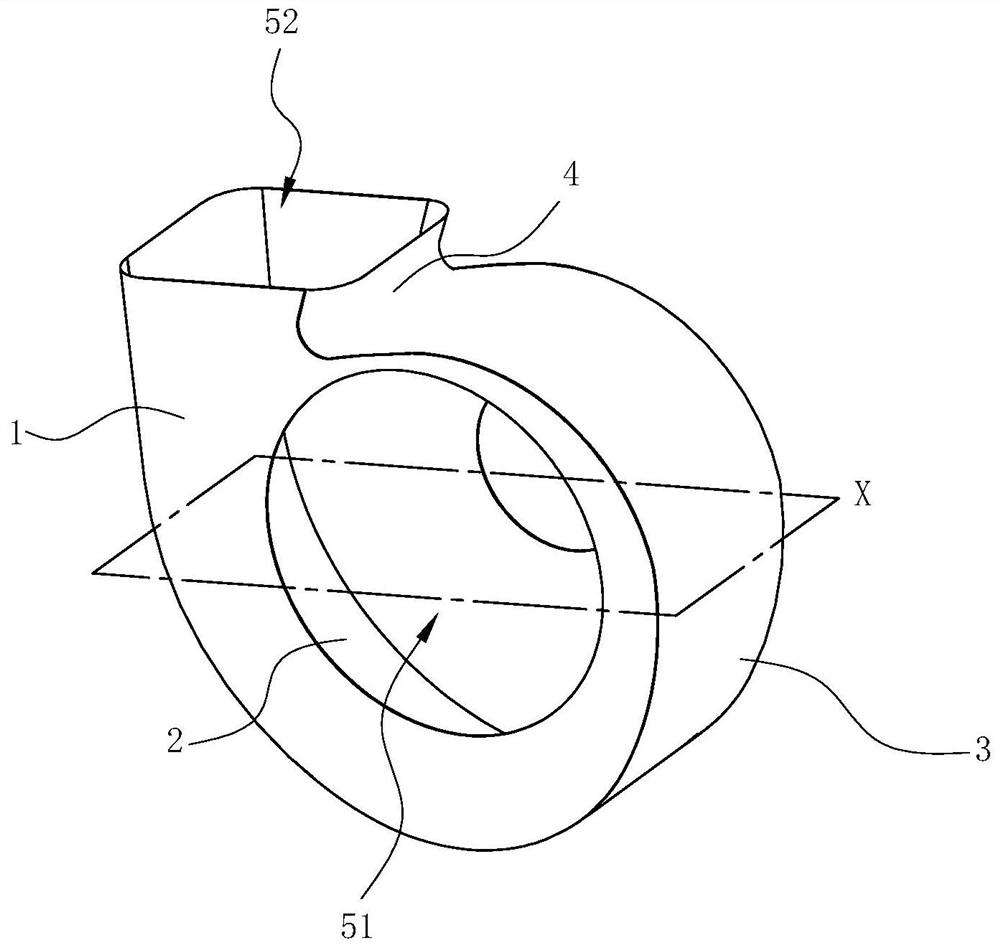
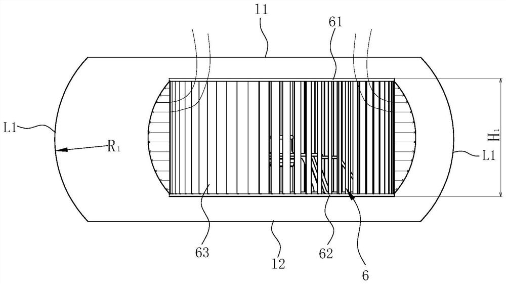
[0019] see figure 1 and figure 2 , a volute for a centrifugal fan, including a front cover 1, a rear cover 2, a ring wall 3 disposed between the front cover 1 and the rear cover 2, and a volute tongue 4. An air inlet 51 and an air outlet 52 are opened on the volute formed by the above components. The centrifugal fan used in the volute further includes an impeller 6 arranged in the volute, and the impeller 6 includes a front disk 61 , a rear disk 62 and a plurality of blades 63 arranged between the front disk 61 and the rear disk 62 .

[0020] The front cover 1 and the rear cover 2 are parallel to each other, and the plane X perpendicular to the front cover 1 and the rear cover 2 and parallel to the air outlet 52 is used as a section (through the ring wall 3, preferably below the volute tongue 4), to obtain For a schematic cross-section of the volute, see figure 2 , on this cross-section X, the profile line of the ring wall 3 is respectively connected to the profile line l...

Embodiment 2

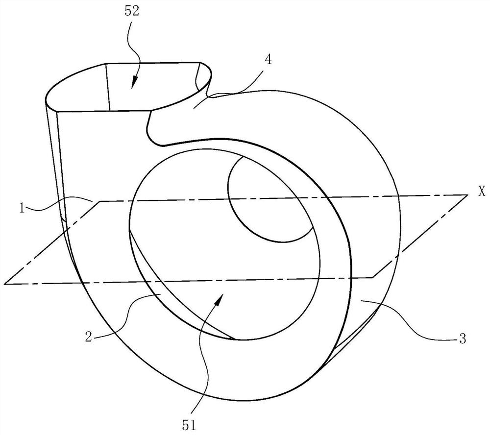
[0024] see image 3 and Figure 4 , in this embodiment, the difference from the first embodiment above is that the profile line of the ring wall 3 on the section X is respectively connected to the corresponding two ends of the profile line l1 of the front cover 1 and the profile line l2 of the rear cover 2 Between the straight line segment L2, the two ends of each straight line segment L2 are respectively connected to the corresponding end of the front cover 1-shaped line l1 through the second circular arc segment L3, and corresponding to the rear cover 2-shaped line l2 through the third circular arc segment L4 The ends are connected, and both the second arc segment L3 and the third arc segment L4 protrude toward the outside of the volute. Preferably, the radii of the second arc segment L3 and the third arc segment L4 are equal, both being R 2 . And preferably, H 2 / 5《R 2 "H 2 / 3, where H 2 is the width of the volute.

[0025] h 2 / 5《R 2 , whose purpose guarantees th...

Embodiment 3

[0027] see Figure 5 and Figure 6 , In this embodiment, the difference from the first embodiment above is that the two ends of each first arc segment L1 are respectively tangent to the corresponding ends of the front cover 1-shaped line l1 and the rear cover 2-shaped line l2.

[0028] In Embodiments 2 and 3, the molded line of the ring wall 3 and the molded line l2 of the front cover 1 and the rear cover 2 are respectively connected by arc segments or tangentially connected, which can effectively eliminate the flow dead zone existing in the volute, Eliminate the vortex at the edge of the volute, effectively improve the aerodynamic efficiency in the volute, increase the air volume, and reduce the aerodynamic noise.


PUM


Abstract

The invention discloses a volute for a centrifugal fan. The volute comprises a front cover and a rear cover which are parallel to each other, and a ring wall connected between the front cover and the rear cover, wherein an air outlet is formed among the front cover, the rear cover and an annular wall, a plane which is perpendicular to the front cover and the rear cover, penetrates through the annular wall, and is parallel to the air outlet is used as a section, on the section, a molded line of the annular wall comprises two line segments connecting the corresponding end portions of a front cover type line and a rear cover type line, and the middles of the line segments are more protruded out of the volute relative to the two ends. The invention further discloses a centrifugal fan using the volute. Compared with the prior art, the volute has the advantages that the annular wall can meet the characteristics that the flow speed of an outlet of an impeller is large in the middle, and small on the two sides, the non-uniform impact of the outlet air flow to the annular wall is weakened, airflow turbulence caused by mutual interference among air flow is reduced, circulation flowing caused by mutual interference among the air flow is eliminated, vortexes are eliminated, the performance of the fan can be effectively improved, and pneumatic noise is reduced.

Description

technical field [0001] The invention relates to a power device, in particular to a centrifugal fan. Background technique [0002] Multi-blade centrifugal fans have the advantages of large flow, high pressure, compact structure, and low noise, and are widely used in areas closely related to daily life such as range hoods and air conditioners. With the improvement of people's quality of life and the industry's higher requirements for home appliance standards, how to effectively increase the air volume, wind pressure, and reduce the noise of multi-blade centrifugal fans has also attracted more and more attention. [0003] The fan is an indispensable core component of the range hood. During the actual operation of the fan, there is a strong unsteady interference between the outlet airflow of the impeller and the wall of the volute, making the wall of the volute the main noise source of the fan. Improving the structure design of the volute and optimizing the flow path can not on...

Claims


Application Information

Patent Timeline
Patent Type & Authority Patents(China)
IPC IPC(8): F04D29/42F04D29/66
CPCF04D29/4226F04D29/667
Inventor 余旭峰时璐璐马志豪
Owner NINGBO FOTILE KITCHEN WARE CO LTD
Why Eureka
Try Eureka