

Light guide plate and preparation method thereof
A light guide plate and substrate technology, applied in the field of light guide plate, can solve the problems of light guide plate material and structure singleness, inability to scatter light uniformly, short service life, etc., to achieve improved thermal stability, improved scattering efficiency, and improved corrosion resistance Effect
- Summary
- Abstract
- Description
- Claims
- Application Information
AI Technical Summary
Problems solved by technology
Method used
Image

Examples
Embodiment 1
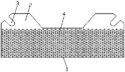
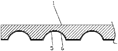
[0026] Such as Figure 1-2 As shown, a light guide plate includes a substrate 1, and a raised portion 2 is respectively provided on both sides of the substrate 1, and the raised portion 2 is integrally formed with the substrate 1, and one side of the raised portion 2 is chamfered. Setting, the chamfering position of the raised portion 2 is provided with a U-shaped mounting hole 3, and the bottom of the substrate 1 is rectangularly arranged with grooves 4, and the cross section of the groove 4 is arranged in a semicircle, so The bottom of the substrate 1 is provided with a PVC glue layer 5 , and the surface of the PVC glue layer 5 is covered with a polymethyl methacrylate particle layer 6 .
[0027] The particle size of the particles in the polymethyl methacrylate particle layer 6 is 0.2-1.2 mm.
[0028] The roughness Ra of the upper surface of the substrate 1 is less than 0.1um.
[0029] The substrate is made of the following materials according to the ratio of parts by mass...
Embodiment 2
[0041] Such as Figure 1-2 As shown, a light guide plate includes a substrate 1, and a raised portion 2 is respectively provided on both sides of the substrate 1, and the raised portion 2 is integrally formed with the substrate 1, and one side of the raised portion 2 is chamfered. Setting, the chamfering position of the raised portion 2 is provided with a U-shaped mounting hole 3, and the bottom of the substrate 1 is rectangularly arranged with grooves 4, and the cross section of the groove 4 is arranged in a semicircle, so The bottom of the substrate 1 is provided with a PVC glue layer 5 , and the surface of the PVC glue layer 5 is covered with a polymethyl methacrylate particle layer 6 .
[0042] The particle size of the particles in the polymethyl methacrylate particle layer 6 is 0.2-1.2 mm.
[0043] The roughness Ra of the upper surface of the substrate 1 is less than 0.1um.
[0044] The substrate is made of the following materials according to the ratio of parts by mass...
Embodiment 3
[0056] Such as Figure 1-2 As shown, a light guide plate includes a substrate 1, and a raised portion 2 is respectively provided on both sides of the substrate 1, and the raised portion 2 is integrally formed with the substrate 1, and one side of the raised portion 2 is chamfered. Setting, the chamfering position of the raised portion 2 is provided with a U-shaped mounting hole 3, and the bottom of the substrate 1 is rectangularly arranged with grooves 4, and the cross section of the groove 4 is arranged in a semicircle, so The bottom of the substrate 1 is provided with a PVC glue layer 5 , and the surface of the PVC glue layer 5 is covered with a polymethyl methacrylate particle layer 6 .
[0057] The particle size of the particles in the polymethyl methacrylate particle layer 6 is 0.2-1.2 mm.
[0058] The roughness Ra of the upper surface of the substrate 1 is less than 0.1um.
[0059] The substrate is made of the following materials according to the ratio of parts by mass...
PUM
| Property | Measurement | Unit |
|---|---|---|
| Particle size | aaaaa | aaaaa |
| Roughness | aaaaa | aaaaa |
| Thickness | aaaaa | aaaaa |
Abstract
Description
Claims
Application Information