Coil assembly of current transformer and production process thereof

A technology of current transformer and coil, applied in the direction of transformer/inductor coil/winding/connection, inductor, transformer/inductor magnetic core, etc., can solve the problem of unreasonable structural design of coil assembly, low qualification rate and production efficiency It can improve the light load error curve, increase the number of coil ampere turns, and achieve stable and reliable performance.

Pending Publication Date: 2019-09-20
DENGGAO ELECTRIC
View PDF0 Cites 1 Cited by
  • Summary
  • Abstract
  • Description
  • Claims
  • Application Information

AI Technical Summary

Problems solved by technology

The current transformer includes a transformer body and a coil assembly arranged in the transformer body. The structure design of the coil assembly of the existing current transformer is unreasonable, the production process is cumbersome, the labor intensity of the workers is high, the production efficiency is low, and The current transformer designed with this structure has a low conversion ratio pass rate of about 60%, and the product pass rate is low, resulting in the defects of high production cost and low pass rate of the current transformer.

Method used


Image

  • Coil assembly of current transformer and production process thereof

Examples


Embodiment Construction

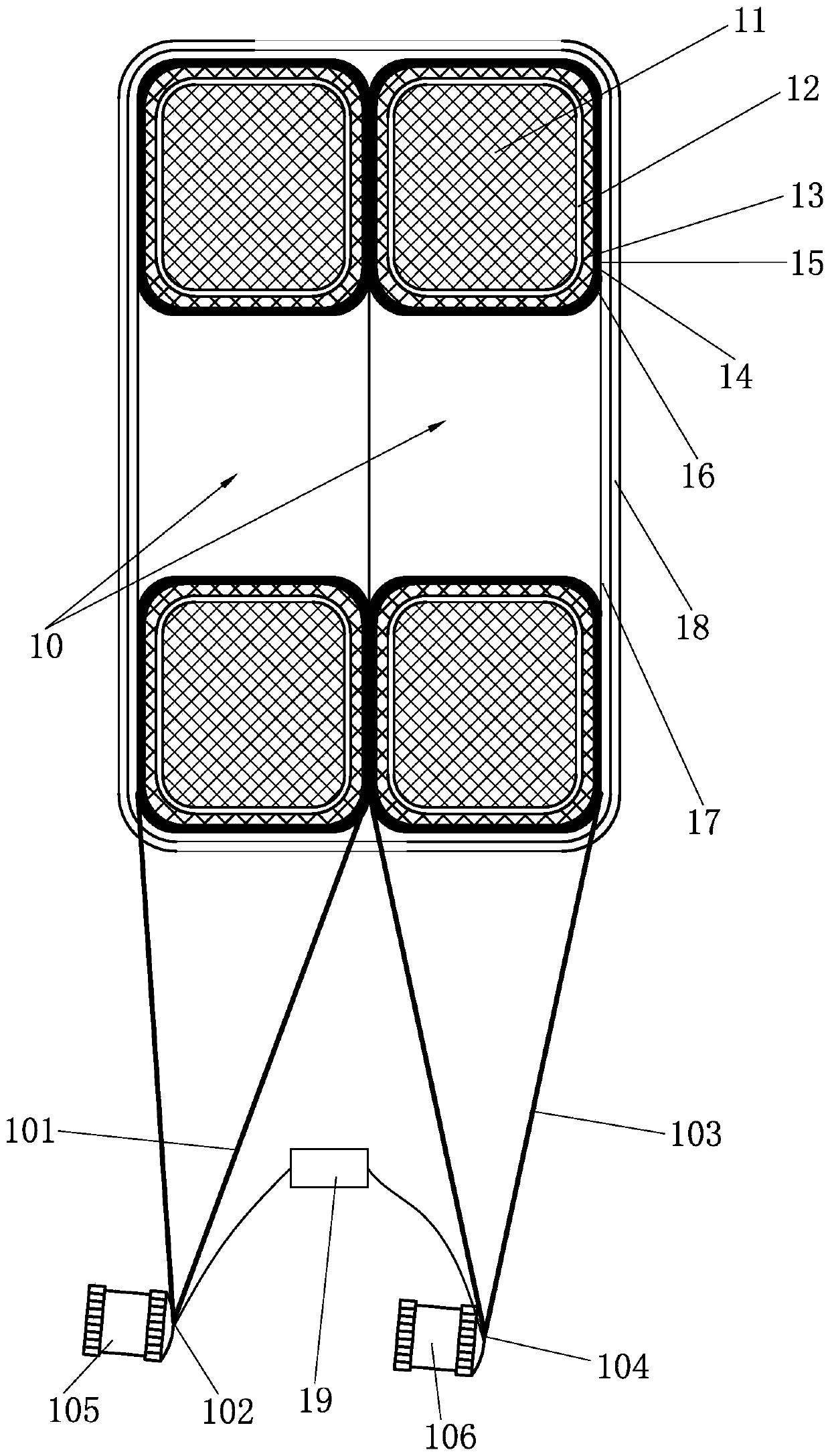
[0017] Such as figure 1 As shown, the embodiment of the present invention is a coil assembly of a current transformer, including two superimposed coil windings 10, and the coil winding 10 includes a main annular iron core 11 wrapped on the main annular iron core 11 The first insulating layer 12, the coil 13 wound on the first insulating layer 12, the compensation ring core 14 arranged inside the coil 13, the second insulation layer 15 wrapped on the compensation ring core 14, wrapped in the coil The third insulating layer 16 on 13, the two coil windings 10 are wrapped with a sponge layer 17, the sponge layer 17 is wrapped with a fourth insulating layer 18, the incoming wires of the two coil windings 10 The lead wires 101 are connected and form an incoming wire end 102. The outgoing wire leads 103 of the two coil windings 10 are connected and form an outgoing wire end 104. The incoming wire end 102 and the outgoing wire end 104 pass through the sponge layer in turn. 17. The fo...


PUM

PropertyMeasurementUnit
Thicknessaaaaaaaaaa

Abstract

The invention relates to a coil assembly of a current transformer. The coil assembly comprises two superimposed coil windings. Each coil winding comprises a main ring iron core, a first insulation layer wrapped on the main ring iron core, a coil wound on the first insulation layer, a compensating ring iron core arranged inside the coil, a second insulation layer wrapped on the compensating ring iron core and a third insulation layer wrapped on the coil. The two coil windings are wrapped by a sponge layer. The sponge layer is wrapped by a fourth insulation layer. Incoming leads of the two coil windings are connected to form a wire incoming end; and outgoing leads of the two coil windings are connected to form a wire outgoing end. The wire incoming end and the wire outgoing end pass through the sponge layer and the fourth insulation layer in sequence and are exposed out of the fourth insulation layer; and the wire incoming end and the wire outgoing end are provided with an incoming copper insert and an outgoing copper insert respectively. The coil assembly has the advantages of simple structure, stable and reliable performance, low production cost and high qualified rate.

Description

technical field [0001] The invention relates to a current transformer, in particular to a coil assembly and a production process of the current transformer. Background technique [0002] A current transformer is an instrument that converts a large current on the primary side into a small current on the secondary side for measurement based on the principle of electromagnetic induction. A current transformer consists of a closed core and windings. The current transformer includes a transformer body and a coil assembly arranged in the transformer body. The structure design of the coil assembly of the existing current transformer is unreasonable, the production process is cumbersome, the labor intensity of the workers is high, the production efficiency is low, and The current transformer designed with this structure has a low conversion ratio pass rate of about 60%, and the product pass rate is low, resulting in the defects of high production cost and low pass rate of the curre...

Claims


Application Information

Patent Timeline
IPC IPC(8): H01F27/28H01F27/29H01F27/32H01F27/40H01F38/30H01F41/04H01F41/076H01F41/08H01F41/12H01F27/24H01F27/245
CPCH01F27/28H01F27/2895H01F27/29H01F27/324H01F27/40H01F38/30H01F41/04H01F41/08H01F41/076H01F41/125H01F27/24H01F27/245H01F2038/305
Inventor 宋思宇黄晓丰张伟葛玲玲张志仁韦云台吴特
Owner DENGGAO ELECTRIC
Why Eureka
Try Eureka