
Charge and discharge control device for ring network cabinet

A charge and discharge control, ring network cabinet technology, applied in the direction of circuit devices, battery circuit devices, substation/power distribution device shells, etc., can solve the problems that the power failure line cannot be restored, the power distribution fault cannot be removed, and the heat dissipation performance of the device is poor. , to achieve good heat dissipation, easy to disassemble and increase the service life

Inactive Publication Date: 2019-09-20
ZHAOTONG POWER SUPPLYING BUREAU OF YUNNAN POWER GRID +1
View PDF7 Cites 3 Cited by
  • Summary
  • Abstract
  • Description
  • Claims
  • Application Information

AI Technical Summary

Problems solved by technology

[0004] Aiming at the deficiencies of the prior art, the present invention provides a charging and discharging control device for the ring network cabinet, which can replace the external power supply for power supply when the external power supply cannot supply power, realizes the charging and discharging of the supercapacitor module, and can continuously Power supply for a large number of users, the heat dissipation performance of the device is good, the installation and disassembly of electrical appliances are more convenient, and the advantages of easy maintenance solve the problem of insufficient power supply in the external power supply of the traditional ring network cabinet, which leads to power distribution faults that cannot be removed, power failure lines cannot be restored, and the device dissipates heat Poor performance, inconvenient disassembly and maintenance

Method used


Image

  • Charge and discharge control device for ring network cabinet
  • Charge and discharge control device for ring network cabinet
  • Charge and discharge control device for ring network cabinet

Examples


Embodiment Construction

[0027] The following will clearly and completely describe the technical solutions in the embodiments of the present invention with reference to the accompanying drawings in the embodiments of the present invention. Obviously, the described embodiments are only some, not all, embodiments of the present invention. Based on the embodiments of the present invention, all other embodiments obtained by persons of ordinary skill in the art without making creative efforts belong to the protection scope of the present invention.

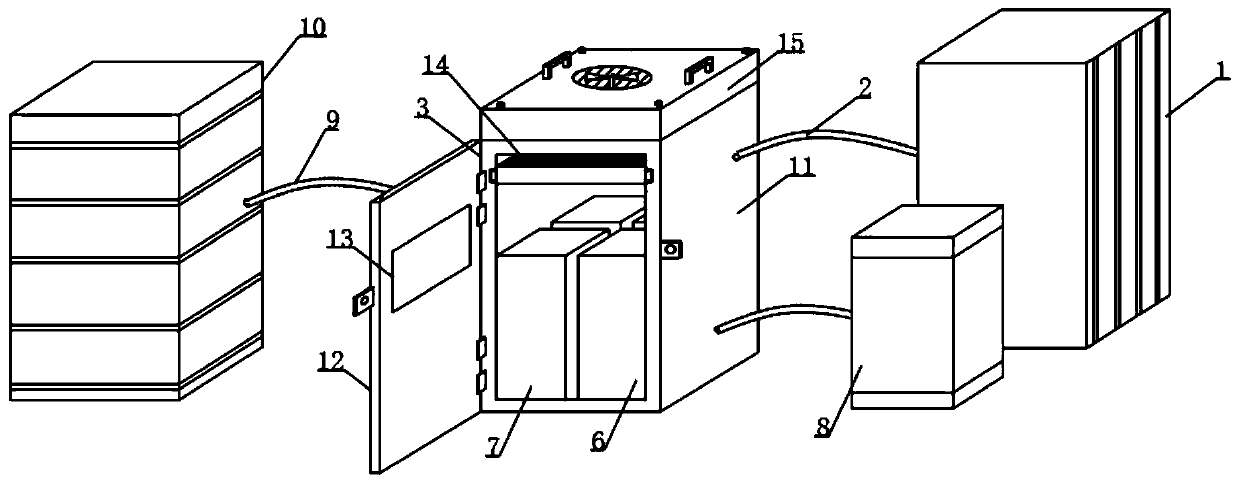
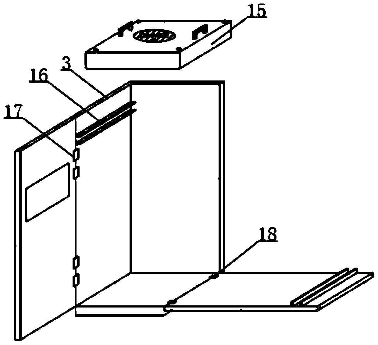
[0028] see Figure 1-5 , a charge and discharge control device for a ring network cabinet, including an external power supply 1, a ring network cabinet protective case 3, a supercapacitor module 5, a voltage detector 4, and the inside of the ring network cabinet protective case 3 is close to the voltage detector 4 A bidirectional DC / DC converter 6 is installed in the front of the ring main unit, a power failure detector 7 is installed in the front of the ring ...


PUM


Abstract

The invention relates to the technical field of power supply, and discloses a charge and discharge control device for a ring network cabinet. The device comprises an external power supply, a ring network cabinet protecting shell, a supercapacitor module and a voltage detector, wherein the internal part of the ring network cabinet protecting shell is equipped with a bidirectional DC / DC converter close to the front of the voltage detector, the internal part of the ring network cabinet protecting shell is equipped with a power failure detector close to the front of the supercapacitor module, the front of the external power supply is equipped with a controller, one end of the ring network cabinet protecting shell is provided with a movable sealing plate, and the inner side of the ring network cabinet protecting shell is provided with heat dissipation fins close to the upper parts of the voltage detector and the supercapacitor module. The charge and discharge control device for the ring network cabinet is good in heat dissipation performance, facilitates the assembly and disassembly of electrical appliances, solves the problems that power distribution faults cannot be removed and the power supply of power failures lines cannot be recovered due to the insufficient power supply of the traditional external power supply, and can continuously supply power to a large number of users.

Description

technical field [0001] The invention relates to the technical field of power supply, in particular to a charging and discharging control device for a ring network cabinet. Background technique [0002] The ring network refers to the ring-shaped distribution network, that is, the main power supply line forms a closed ring, and the power supply supplies power to the ring-shaped main line, and then distributes power from the main line through the high-voltage switch all the way. The advantage of this is that each power distribution The branch circuit can get power from the main line on one side and the main line on the other side. When the main line on one side fails, it will continue to receive power from the main line on the other side. If there is a fault, it will continue to receive power from one side of the main line. In this way, although the total power supply is a single-circuit power supply, each distribution branch can get benefits similar to dual-circuit power suppl...

Claims


Application Information

Patent Timeline
IPC IPC(8): H02B1/30H02B1/38H02J7/00H05K7/20
CPCH02B1/30H02B1/38H02J7/0042H02J7/345H05K7/20909
Inventor 陇辉汪波赵泽彪邱平兰静波江东君
Owner ZHAOTONG POWER SUPPLYING BUREAU OF YUNNAN POWER GRID
Learn More