
A device power supply protection circuit and control method

A technology of power protection and relay control, applied in the field of electronics, can solve the problems of high development cost and high maintenance cost.

Active Publication Date: 2021-09-17
深圳市大族封测科技股份有限公司
View PDF3 Cites 0 Cited by
  • Summary
  • Abstract
  • Description
  • Claims
  • Application Information

AI Technical Summary

Problems solved by technology

[0003] Currently, the power protection modules on the market are mainly controlled by microprocessor timers. The development cost of this design is relatively high and the later maintenance cost is also relatively high.

Method used


Image

  • A device power supply protection circuit and control method
  • A device power supply protection circuit and control method
  • A device power supply protection circuit and control method

Examples


Embodiment 1

[0055] Embodiments of the present application provide a device power supply protection circuit and a control method, which are used to provide grid undervoltage protection and power supply delay protection against voltage shocks.

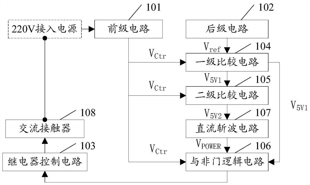
[0056] see figure 1 , the equipment power supply protection circuit mainly includes the following modules:

[0057] Pre-stage circuit 101, post-stage circuit 102, relay control circuit 103, primary comparison circuit 104, secondary comparison circuit 105, and NAND logic circuit 106;

[0058] The pre-stage circuit 101 is used to process the incoming power supply and generate a comparison voltage V Ctr The access power supply is the access power supply of the protected equipment; the front-stage circuit includes: a step-down module, a rectification module, a voltage stabilization module and a voltage divider module; the access power supply is rectified by the step-down module After being processed by the module and the voltage stabilizing module, a ...

Embodiment 2

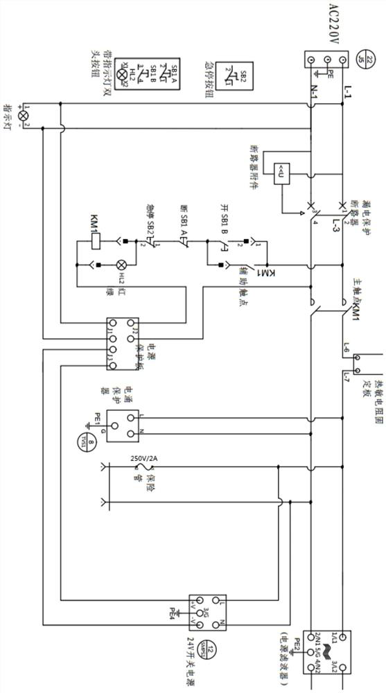
[0077] For ease of understanding, the embodiment of this application provides an application example of the device power supply protection circuit, please refer to figure 2 , figure 2 An application electrical diagram for the equipment power protection circuit, including:

[0078] exist figure 2 In the circuit shown, the pre-stage circuit, the post-stage circuit and the relay control circuit are connected through the interface in the power protection board in the figure. Among them, the J1 port is the input terminal of 220V AC in the pre-stage circuit, and the J3 port is the post-stage circuit. The input terminal of the 24V switching power supply, the J2 port is the output terminal of the relay, the closing and opening of the relay controls the on-off of the power supply of the equipment.

[0079] As shown in the figure, in the pre-stage circuit, a leakage protection circuit breaker and circuit breaker accessories are provided for leakage protection of the circuit. After t...

Embodiment 3

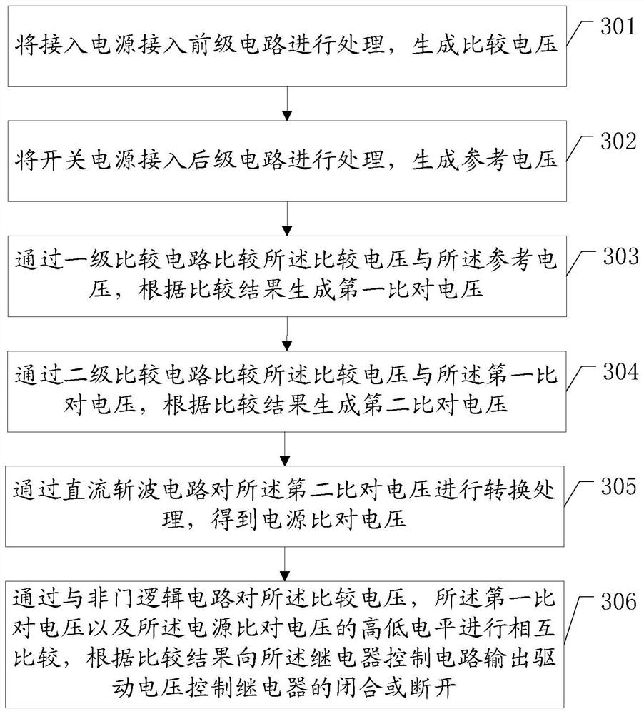
[0084] see image 3 , the control method corresponding to the device power supply protection circuit in the embodiment of the present application, including:

[0085] 301. Connect the incoming power to the pre-stage circuit for processing to generate a comparison voltage;


PUM


Abstract

An equipment power supply protection circuit and a control method, wherein the equipment power supply protection circuit includes: a pre-stage circuit, a post-stage circuit, a relay control circuit, a primary comparison circuit, a secondary comparison circuit, and a NAND gate logic circuit; the pre-stage circuit It is used to process the incoming power supply to generate a comparison voltage; the subsequent stage circuit is used to process the switching power supply to generate a reference voltage; the primary comparison circuit is used to generate the first A comparison voltage; the secondary comparison circuit is used to generate a second comparison voltage according to the comparison result between the comparison voltage and the first comparison voltage; the NAND logic circuit is used to generate the first comparison voltage and the second comparison voltage according to the comparison voltage Comparing the mutual comparison results of the voltages, outputting the driving voltage to the relay control circuit; the relay control circuit is used to control the closing or opening of the relay according to the driving voltage, so as to protect the protected equipment.

Description

technical field [0001] The present application relates to the field of electronic technology, and in particular to a device power supply protection circuit and a control method. Background technique [0002] With the rapid development of society, human beings use electronic products more and more widely. As an important part of energy supply, power modules are used more and more in the entire electronic field. With the continuous increase in the variety of automation equipment, various types of electrical appliances have higher and higher design requirements for power modules. The traditional transformer and filter design that has been used has been unable to adapt to the rapidly changing market demand in the increasingly complex product research and development system. Therefore, a power protection module appears in the circuit design. The significance of the design of the power protection module lies in: when the grid voltage is lower than the normal power supply range,...

Claims


Application Information

Patent Timeline
Patent Type & Authority Patents(China)
IPC IPC(8): H02H3/247H02H7/12
CPCH02H3/247H02H7/1203
Inventor 梁付根李宝平朱绍德高云峰
Owner 深圳市大族封测科技股份有限公司
Learn More