Dust removal device for computer hardware

A technology of dust removal device and hardware, applied in the direction of cleaning method using tools, cleaning method using gas flow, cleaning method and utensils, etc., can solve problems such as difficulty in starting up, the brush head is too large, and polluting the environment, so as to avoid accumulation, The effect of reducing the life of the device

Inactive Publication Date: 2019-09-24
西安哈希码信息技术有限公司
View PDF1 Cites 5 Cited by
  • Summary
  • Abstract
  • Description
  • Claims
  • Application Information

AI Technical Summary

Problems solved by technology

[0002] During the use of desktop computers, dust will slowly enter the chassis and scatter on the computer motherboard, hard disk, memory stick and other related hardware. After a long period of accumulation, it will lead to poor internal electrical contact and slow heat dissipation, causing the computer to run slowly and even difficult to boot
In some computer repair shops, hair dryers are often used to clean the internal hardware of the case. Although a certain amount of dust can be removed, some dust that is tightly adsorbed is difficult to remove with wind.
[0003] Existing Chinese patent CN207693175U has proposed a kind of computer hardware dedusting device, and this device cooperates with replacing horizontal bristle or vertical bristle through slender blower pipe, turns on the switch of electric fan, and wind blows fan blade to rotate, drives horizontal brush or The vertical brush rotates, and the remaining wind power can be blown out from the blowing hole to remove the dust that is not easy to clean in the corners of the chassis, but the patent still has the following two problems; first: the dust is scattered around during the computer dust removal process , pollute the environment; second: the dust accumulated in the dust removal equipment in the later period is not easy to clean out; third: the brush head is too large, and there is no great cleaning power when cleaning some subtle places

Method used


Image

  • Dust removal device for computer hardware
  • Dust removal device for computer hardware
  • Dust removal device for computer hardware

Examples


Embodiment Construction

[0016] In order to make the technical means, creative features, goals and effects achieved by the present invention easy to understand, the present invention will be further described below in conjunction with specific embodiments.

[0017] The technical solutions in the embodiments of the present invention will be clearly and completely described below in conjunction with the accompanying drawings in the embodiments of the present invention. Obviously, the described embodiments are only some of the embodiments of the present invention, not all of them. Based on The embodiments of the present invention and all other embodiments obtained by persons of ordinary skill in the art without making creative efforts belong to the protection scope of the present invention.

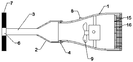
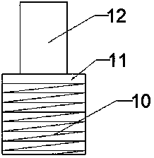
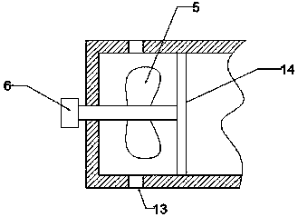
[0018] see Figure 1 to Figure 3 , the present invention provides a technical solution: a dust removal device for computer hardware, including a casing 1, a tapered sleeve 2, a blowing pipe 3, a locking device 4, fa...


PUM


Abstract

The invention discloses a dust removal device for a computer hardware. The dust removal device comprises a machine shell, a conical sleeve, an air blowing pipe, a locking device, fan blades, a connecting block, a vertical brush, a switch, an electric fan, a compression spring, a limiting plate, a locking column, an air blowing hole, a fixed rod, a filter screen, an end cover, a cleaning sponge, a storage box, a spare cleaning head, a small cleaning brush and a rubber cleaning head; the machine shell is of a circular-tube-shaped structure, the left end of the machine shell is fine, the right end of the machine shell is thick, and the storage box is fixedly arranged at the bottom of the machine shell. According to the dust removal device, the switch of the electric fan is opened through the cooperation of the elongated air blowing pipe and the vertical brush, the wind power blows the fan blades to rotate so as to drive the vertical brush to rotate, the residual wind power can also be blown out of the air blowing hole, and dust in the corner of a case is cleared away; and the air blowing pipe can be detached through the locking device, and the dust which is easy to clean on the surface is directly cleaned by the electric fan.

Description

technical field [0001] The invention relates to the field of dust removal for computer hardware, in particular to a dust removal device for computer hardware. Background technique [0002] During the use of desktop computers, dust will slowly enter the chassis and scatter on the computer motherboard, hard disk, memory stick and other related hardware. After a long period of accumulation, it will lead to poor internal electrical contact and slow heat dissipation, causing the computer to run slowly and even difficult to boot . In some computer repair shops, a hair dryer is often used to clean the internal hardware of the case. Although a certain amount of dust can be removed, some dust that is tightly adsorbed is difficult to remove with wind. [0003] Existing Chinese patent CN207693175U has proposed a kind of computer hardware dedusting device, and this device cooperates with replacing horizontal bristle or vertical bristle through slender blower pipe, turns on the switch o...

Claims


Application Information

Patent Timeline
Patent Type & Authority Applications(China)
IPC IPC(8): B08B1/00B08B1/04B08B5/02B01D46/10
CPCB01D46/10B08B1/002B08B1/006B08B1/04B08B5/02
Inventor 杨云龙
Owner 西安哈希码信息技术有限公司
Why Eureka
Try Eureka