
Compounding machine control device

A control device and compound machine technology, applied in lamination devices, control lamination, lamination, etc., can solve problems such as insecurity, unstable product quality control, waste of manpower, etc., and achieve increased safety, DC and AC conversion The effect of convenience and simple structure

Inactive Publication Date: 2019-09-24
肖文兵
View PDF0 Cites 0 Cited by
  • Summary
  • Abstract
  • Description
  • Claims
  • Application Information

AI Technical Summary

Problems solved by technology

In the traditional lamination machine, the glue residue left by the laminating roller needs to be removed manually by the operator with a blade, which is a waste of manpower and unsafe, and it is unstable for product quality control

Method used


Image

  • Compounding machine control device
  • Compounding machine control device
  • Compounding machine control device

Examples


Embodiment Construction

[0017] The following will clearly and completely describe the technical solutions in the embodiments of the present invention with reference to the accompanying drawings in the embodiments of the present invention. Obviously, the described embodiments are only some of the embodiments of the present invention, but not all of them. Based on the embodiments of the present invention, all other embodiments obtained by persons of ordinary skill in the art without making creative efforts belong to the protection scope of the present invention.

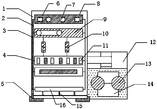
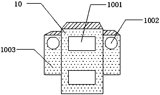
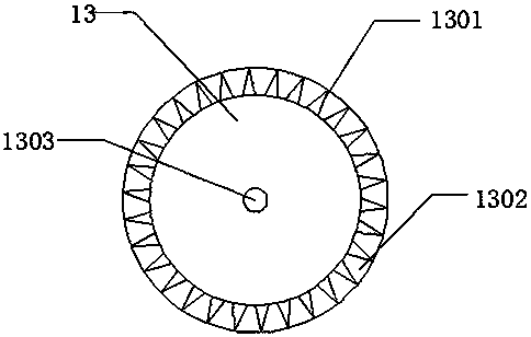
[0018] The present invention provides such figure 1 , figure 2 and image 3 The compound machine control device shown includes a cabinet body 1, a connection line 2 is provided on the right side of the lower part of the cabinet body 1, and wire slots 3 are connected to the left and right sides of the connection line 2, and the wire slots 3 A connecting rod 4 is fixed on the right side of the lower part, a base 5 is fixed on the left side o...


PUM


Abstract

The invention discloses a compounding machine control device. The device comprises a cabinet body, the left side and the right side of a connecting wire are connected with wire slots, a connecting rod is fixed on the lower right sides of the wire slots, a pedestal is fixed at the lower left side of the connecting rod, a positioning plate is arranged at the upper right side of the pedestal, a relay group is arranged inside the positioning plate, a conductive screw is fixed at the upper left side of the relay group, control panels are arranged at the left side and the right side of the lower part of the conductive screw, the lower left side of the control panel is connected with protectors, circuit boards are fixed at the left side and the right side of the lower parts of the protectors, the lower right side of the circuit boards is connected with a motor cover, the lower left side of the motor cover is fixedly provided with rotors, the rotors are connected with a wire group controller, the lower left side of the wire group controller is connected with output wires, and an exchanger is fixed at the upper left sides of the output wires. The compounding machine control device has a simple structure and practical functions.

Description

technical field [0001] The invention belongs to the technical field of compound machine control, and in particular relates to a compound machine control device. Background technique [0002] The composite machine is to heat two or more layers of the same or different materials such as cloth and cloth, cloth and paper, cloth and artificial leather, and various plastics and rubber sheets to a melted, semi-melted state or use a special Adhesives bonded together into one machine. Composite machines are widely used in home textiles, clothing, furniture, automotive interiors and other related industries. They are mainly used for two-layer or multi-layer lamination production processes of various types of cloth, leather, film, paper, sponge, etc. Specifically, it can be divided into glue compound and glueless compound. Glue compound can be divided into water glue, PU oil glue, hot melt glue, etc. The glueless compound process is mostly direct hot pressing bonding between materials...

Claims


Application Information

Patent Timeline
Patent Type & Authority Applications(China)
IPC IPC(8): B32B37/06B32B37/12B32B41/00
CPCB32B37/06B32B37/12B32B41/00
Inventor 肖文兵
Owner 肖文兵
Learn More