
Annular material receiving device and distributing method thereof

A material receiving device and material distribution technology, applied in the direction of furnace type, furnace, continuous charging, etc., can solve problems such as inconsistent thickness, affecting the process, reducing the proportion of reduced iron, etc., to ensure normal operation, improve production efficiency and product quality, The effect of uniform cloth

Pending Publication Date: 2019-09-24
CHONGQING CISDI THERMAL & ENVIRONMENTAL ENG CO LTD +1
View PDF0 Cites 0 Cited by
  • Summary
  • Abstract
  • Description
  • Claims
  • Application Information

AI Technical Summary

Problems solved by technology

The existing feeding device drives the material on the bottom plate of the feeding device box with a given vibration frequency and amplitude to distribute the material at a uniform speed in the width direction of the box. However, during the rotation of the ring furnace, due to the ring shape At a given rotation speed of the bottom of the furnace, the linear speed of each point along the radial direction increases from the inner ring to the outer ring. In this case, the existing feeding device is used, and the speed in the width direction of the feeding device is consistent. The material distribution at the bottom of the furnace will cause the materials to accumulate more and thicker on the ring-shaped bottom near the inner ring, and the materials near the outer ring will accumulate less and thinner. The thickness is inconsistent, which will lead to low production efficiency of the ring furnace, over-reaction of the thinner part of the cloth, insufficient reduction of the thicker part of the cloth, reducing the proportion of reduced iron, seriously affecting the normal process of the process, and the product cannot meet the requirements quality

Method used


Image

  • Annular material receiving device and distributing method thereof
  • Annular material receiving device and distributing method thereof

Examples


Embodiment Construction

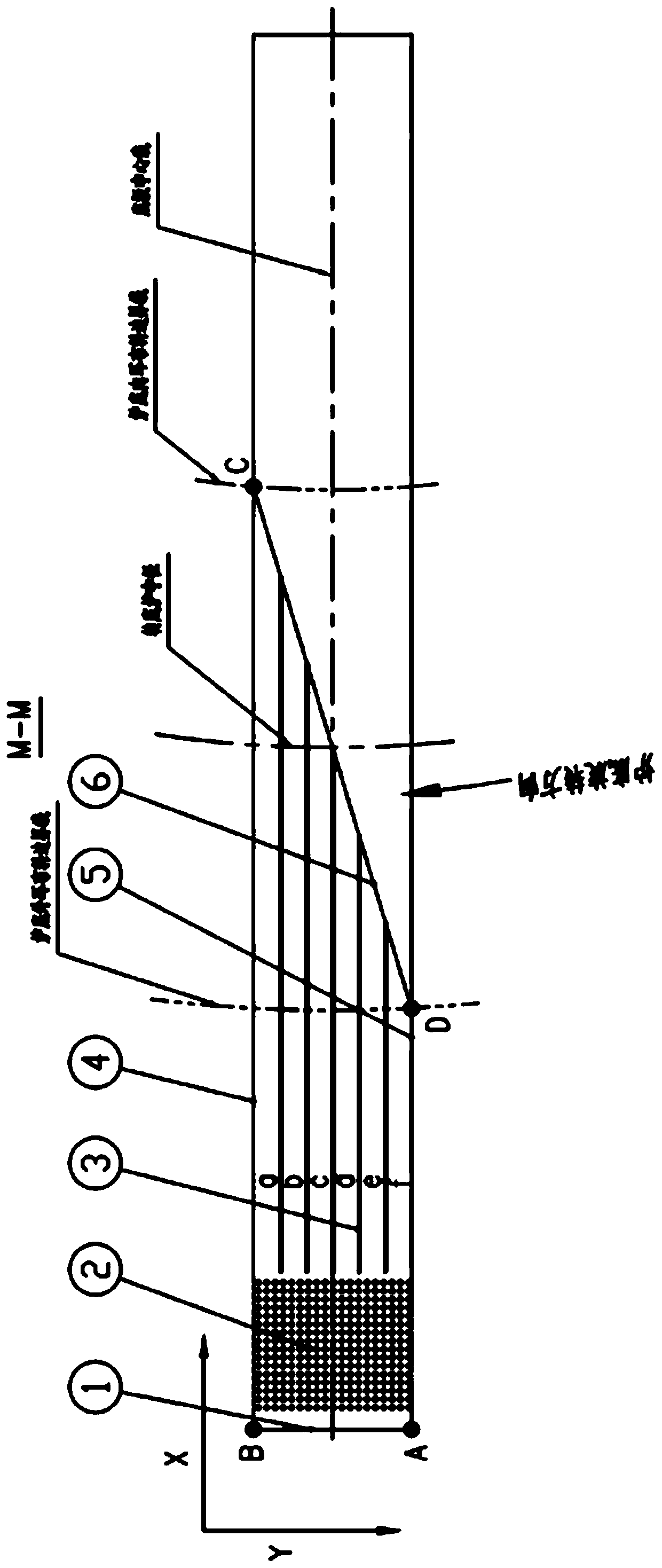
[0017] Embodiments of the present invention are described below through specific examples, and those skilled in the art can easily understand other advantages and effects of the present invention from the content disclosed in this specification. The present invention can also be implemented or applied through other different specific implementation modes, and various modifications or changes can be made to the details in this specification based on different viewpoints and applications without departing from the spirit of the present invention. It should be noted that the diagrams provided in the following embodiments are only schematically illustrating the basic concept of the present invention, and the following embodiments and the features in the embodiments can be combined with each other in the case of no conflict.

[0018] Such as figure 1 , 2 As shown, the present invention provides an annular material receiving device consisting of a vibrating box 8, a vibrator 7, a d...


PUM


Abstract

The invention discloses an annular material receiving device and a distributing method thereof and belongs to the technical field of annular furnace feeding. The device comprises a vibration box body, a vibration exciter, a distributing base plate with an inclined curved structure and a material separating baffle. The inclined curved structure of the distributing base plate is as follows: the inclined curved structure obliquely faces downward in the width direction of the vibration box body along the rotating reverse direction of the furnace bottom and in the length direction of the vibration body along the direction of an outer ring to an inner ring of the furnace bottom, and the surface curvature is gradually increased. According to the method, an inclined curved surface of the distributing base plate at the bottom of the vibration box body is used and is matched with the furnace bottom for rotating under the drive of given vibration frequency and amplitude; in the width direction of the vibration box body, materials fall into the furnace bottom at different discharging speeds; the materials with high discharging speed fall into the outer ring of the furnace bottom, and the materials with low discharging speed fall into the inner ring of the furnace bottom. According to the annular material receiving device and the distributing method thereof disclosed by the invention, the materials can be uniformly arranged at the circular rotary furnace bottom of an annular furnace, so that all parts of the materials on the furnace bottom are consistent in thickness, and the production efficiency and the product quality of the annular furnace are ensured.

Description

technical field [0001] The invention belongs to the technical field of feeding materials to an annular furnace, and relates to an annular material receiving device and a method for distributing materials thereof, which are suitable for metallurgy, mining, coal, building materials and other industries. Background technique [0002] In the direct reduction process of the rotary bottom annular furnace in the field of iron and steel metallurgy, the reduction reaction is carried out at the bottom of the rotary furnace, and the rotary bottom of the annular furnace is circular. The bottom of the furnace needs to be covered with materials to be directly reduced, and the thickness of the materials on the bottom of the furnace should be as consistent as possible. The existing feeding device drives the material on the bottom plate of the feeding device box with a given vibration frequency and amplitude to distribute the material at a uniform speed in the width direction of the box. How...

Claims


Application Information

Patent Timeline
Patent Type & Authority Applications(China)
IPC IPC(8): F27B13/06F27D3/00
CPCF27B13/06F27D3/00F27M2002/11F27D2003/0038
Inventor 向礼江雍海泉王华林陆大成
Owner CHONGQING CISDI THERMAL & ENVIRONMENTAL ENG CO LTD
Learn More