
Monitoring system for grounding running state of distribution network distribution area equipment

A technology for monitoring system and operating status, applied in the field of electric power, can solve the problems of low monitoring degree, incomplete data, low automation and intelligence, etc., and achieve the effect of high real-time monitoring degree, high degree of automation, and safety guarantee.

Active Publication Date: 2019-09-24
河南四达检测技术有限公司 +1
View PDF12 Cites 0 Cited by
  • Summary
  • Abstract
  • Description
  • Claims
  • Application Information

AI Technical Summary

Problems solved by technology

However, in the actual work process, the traditional working method can no longer meet the actual work needs, resulting in serious problems in the management of the station area: 1. The data is not comprehensive; 2. The level of equipment automation is low; 3. The intelligence of the distribution station area Low level of culture, etc.;
[0007] Third, real-time, detailed and accurate monitoring of arrester current, graphite grounding band resistance, JP cabinet surface current, and graphite grounding band current cannot be fully realized. Whether the grounding operation status is good cannot be guaranteed, and various data signals cannot be monitored and well The rapid response makes the PC client unable to evaluate the monitoring results and take emergency measures. The low degree of monitoring will cause paralysis of the distribution network area, fault error reporting or delay, and seriously affect the power consumption of the distribution network area. Automation and intelligence low level

Method used


Image

  • Monitoring system for grounding running state of distribution network distribution area equipment
  • Monitoring system for grounding running state of distribution network distribution area equipment
  • Monitoring system for grounding running state of distribution network distribution area equipment

Examples


Embodiment Construction

[0040] Specific examples are given below to further describe the technical solution of the present invention in a clear, complete and detailed manner. This embodiment is the best embodiment on the premise of the technical solution of the present invention, but the protection scope of the present invention is not limited to the following embodiments.

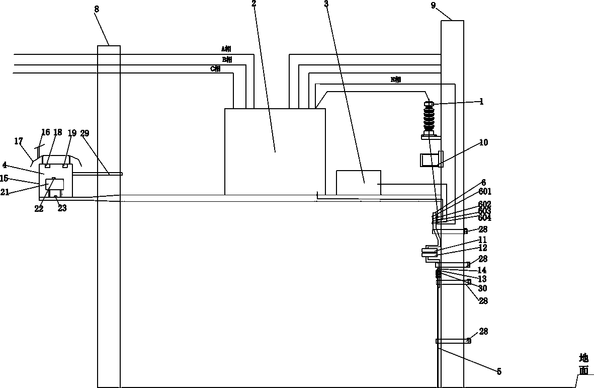
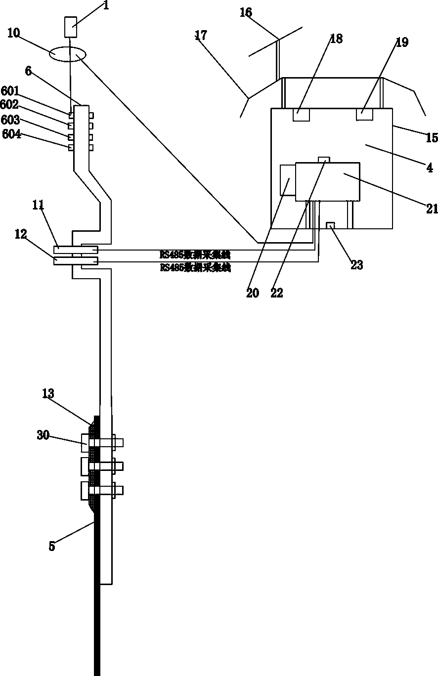
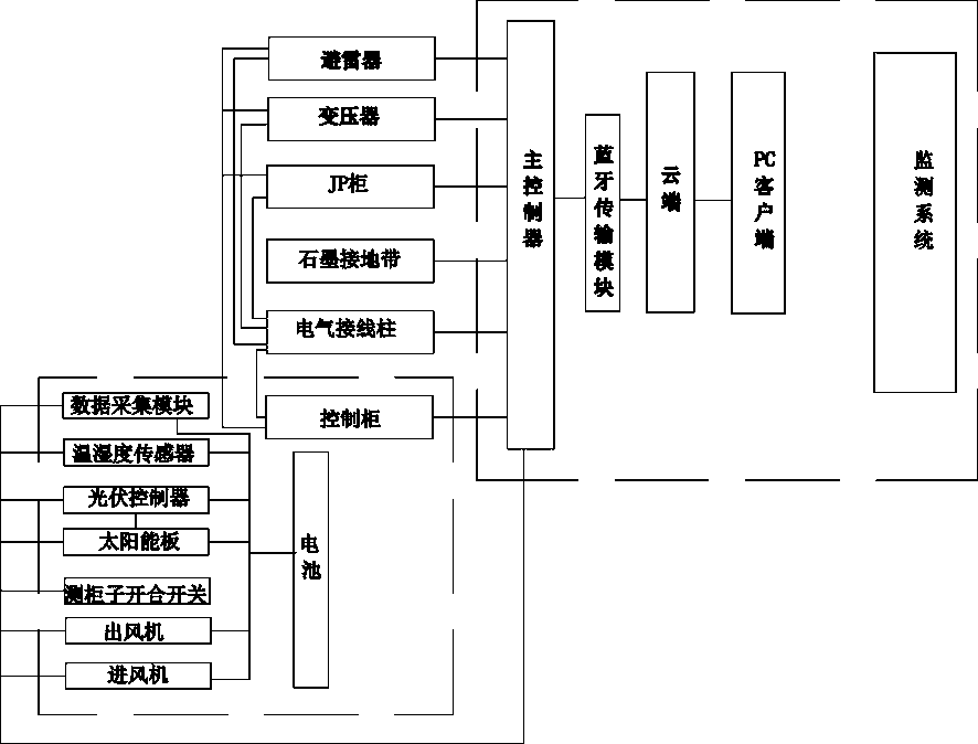
[0041] A system for monitoring the grounding operation status of equipment in a distribution network station area, including a lightning arrester 1, a transformer 2, a JP cabinet 3, a control cabinet 4, a graphite grounding belt 5, an electrical terminal 6, and a monitoring system 7. The lightning arrester 1, the transformer 2, JP cabinet 3, control cabinet 4, graphite grounding belt 5, and electrical terminal 6 are all connected to the monitoring system 7; each module cooperates closely with the logic to form an efficient monitoring network, ensuring the effectiveness of the grounding operation of the entire distribution network ...


PUM


Abstract

The invention discloses a monitoring system for the grounding running state of distribution network distribution area equipment. The monitoring system comprises a lightning arrester, a transformer, a JP cabinet, a control cabinet, a graphite grounding strip, an electric binding post and a monitoring system, wherein the lightning arrester, the transformer, the JP cabinet, the control cabinet, the graphite grounding strip and the electric binding post are all connected with the monitoring system; the monitoring system achieves the real-time monitoring of the current of the lightning arrester, the resistance of the graphite grounding strip, the current of the surface of the JP cabinet and the current of the graphite grounding strip, is efficient and accurate, is quick in response and high in real-time monitoring degree, and a PC client can evaluate the monitoring result and take emergency measures, so that the high safety of the equipment in a distribution network area is ensured, and the monitoring system is more automatic and intelligent.

Description

technical field [0001] The invention belongs to the field of electric power, and relates to equipment management technology in a distribution network area, in particular to a monitoring system for grounding operation status of equipment in a distribution network area. Background technique [0002] The development of electric power enterprises is of great significance to the development of social economy, and the good development of electric power enterprises is the internal driving force of my country's economic development. In the actual power supply management work, it is of great significance to actively strengthen the work analysis of line loss, which can promote the development of power supply enterprises and improve the quality of power supply in our country. However, in the actual power supply management process, there are still some problems, which seriously affect the development of related work. The construction of the equipment detection system in the distributio...

Claims


Application Information

Patent Timeline
IPC IPC(8): G01R31/02G01R31/08G01D21/02G08C17/02H02J7/35
CPCG01R31/086G01D21/02G08C17/02H02J7/35G01R31/50
Inventor 陈瑞斌姜兴昌谭兴华乔卫良岳志磊张明磊方腾龙贺旭东张帅
Owner 河南四达检测技术有限公司
Learn More