Power factor correction circuit and vehicle-mounted charger

A power factor correction and circuit technology, applied in electric vehicles, circuit devices, battery circuit devices, etc., can solve the problems of high cost and large volume of the three-arm PFC circuit, and achieve cost reduction, volume reduction, and capacitor volume reduction small effect

Pending Publication Date: 2019-09-24
SUZHOU INOSA UNITED POWER SYST CO LTD
View PDF0 Cites 7 Cited by
  • Summary
  • Abstract
  • Description
  • Claims
  • Application Information

AI Technical Summary

Problems solved by technology

[0004] The present invention provides a power factor correction circuit, which is used to solve the problem of large volume and high cost of the three-bridge PFC circuit due to power frequency ripples in the output current when the existing three-bridge PFC circuit works in the single-phase AC input mode. The problem

Method used


Image

  • Power factor correction circuit and vehicle-mounted charger
  • Power factor correction circuit and vehicle-mounted charger
  • Power factor correction circuit and vehicle-mounted charger

Examples


Embodiment Construction

[0043] In order to make the purpose, technical solutions and advantages of the embodiments of the present invention clearer, the embodiments of the present invention will be further described in detail below in conjunction with the accompanying drawings and embodiments. It should be understood that the specific embodiments described here are only used to explain the embodiments of the present invention, and are not intended to limit the embodiments of the present invention.

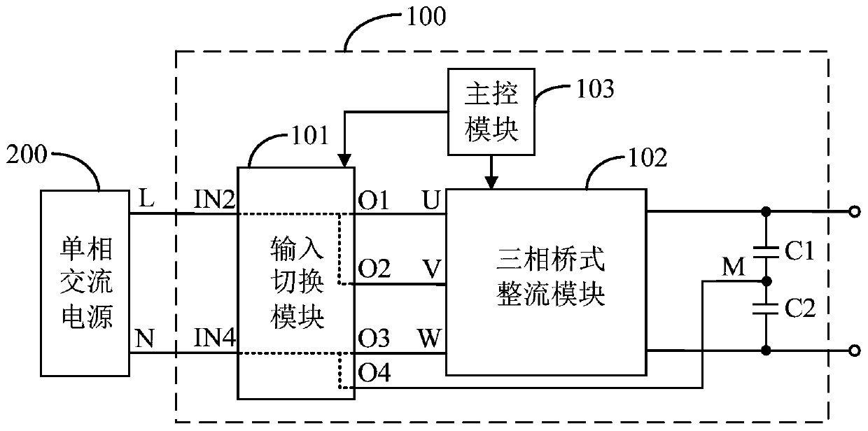
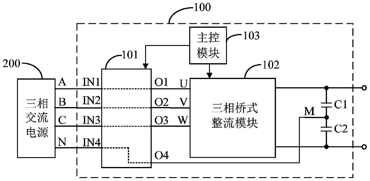
[0044] figure 2 It is a schematic diagram of a power factor correction circuit 100 provided by an embodiment of the present invention. The power factor correction circuit 100 includes an input switching module 101, a three-phase bridge rectification module 102, a main control module 103, a first capacitor C1 and a second capacitor C2.

[0045] The first end of the first capacitor C1 and the first end of the second capacitor C2 are respectively connected to the first output end and the second output end o...


PUM


Abstract

The invention discloses a power factor correction circuit and a vehicle-mounted charger. The power factor correction circuit comprises an input switching module, a three-phase bridge rectifier module, a main control module, a first capacitor and a second capacitor. When the power factor correction circuit is powered by a single-phase AC power supply, the input switching module executes first line switching, so that a live line of the single-phase AC power supply is enabled to be connected with a first input end and a second input end of the three-phase bridge rectifier module through the input switching module, and a neutral line of the single-phase AC power supply is enabled to be connected with a third input end of the three-phase bridge rectifier module and a capacitor midpoint through the input switching module; and the three-phase bridge rectifier module rectifies the single-phase AC power supply and realizes power factor correction, and one bridge arm thereof generates power frequency compensation current. The power frequency compensation current in the bridge arm can eliminate power frequency ripples in the output current of the three-phase bridge rectifier module, so that an output capacitor with smaller capacity can be adopted, the size can be effectively reduced, and the cost is reduced.

Description

technical field [0001] The invention relates to the technical field of electronic circuits, in particular to a power factor correction circuit and a vehicle charger. Background technique [0002] Power Factor Correction (PFC) circuit is an electronic circuit used to improve the power factor of electrical equipment in the field of power electronics. With the continuous development of power electronics technology, miniaturization, low cost, and high efficiency have become its The direction of continuous development. [0003] In the prior art, the PFC circuit topology compatible with single-phase AC and three-phase AC input is as follows: figure 1 As shown, the topology of the PFC circuit is a three-leg PFC circuit, and a relay is installed at the AC input end, and the switching between single-phase AC input and three-phase AC input is realized through the opening and closing of the relay. When the three-leg PFC circuit works in the single-phase AC input mode, two of the brid...

Claims


Application Information

Patent Timeline
Patent Type & Authority Applications(China)
IPC IPC(8): H02M1/42H02J7/10
CPCH02J7/06H02J2007/10H02M1/4233Y02B70/10
Inventor 姚云鹏
Owner SUZHOU INOSA UNITED POWER SYST CO LTD
Why Eureka
Try Eureka