Pump-driven two-phase loop heat dissipation system for high-power-density cabinet

A technology of high power density and heat dissipation system, which is applied in the field of pump drive two-phase loop heat dissipation system, to achieve the effect of improving utilization rate, saving floor space and reducing complexity

Active Publication Date: 2019-09-24
BEIHANG UNIV
View PDF10 Cites 6 Cited by
  • Summary
  • Abstract
  • Description
  • Claims
  • Application Information

AI Technical Summary

Problems solved by technology

[0006] Aiming at the defects of the above-mentioned prior art, the present invention provides a pump-driven two-phase loop heat dissipation system for high power density cabinets. This system can dissipate heat for the main heating elements of the server,

Method used


Image

  • Pump-driven two-phase loop heat dissipation system for high-power-density cabinet
  • Pump-driven two-phase loop heat dissipation system for high-power-density cabinet
  • Pump-driven two-phase loop heat dissipation system for high-power-density cabinet

Examples


Embodiment Construction

[0034] The present invention will be further described below in conjunction with the accompanying drawings and specific embodiments. It should be understood that the following embodiments are intended to facilitate the understanding of the present invention, and have no limiting effect on it.

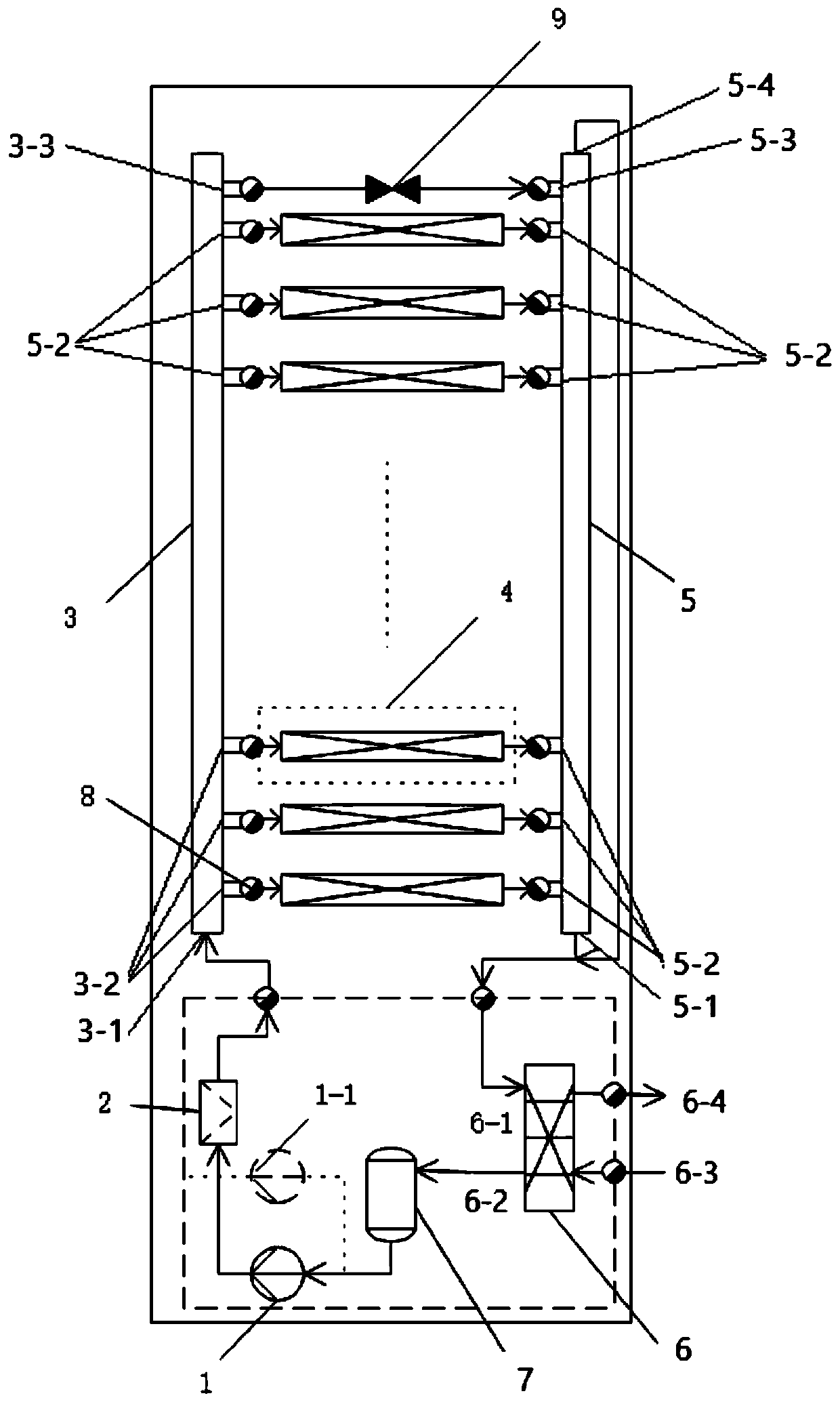
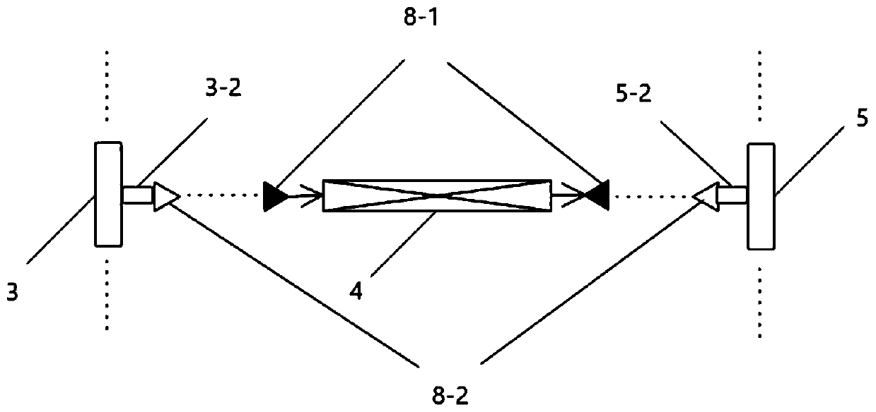
[0035] Such as figure 1 As shown, the pump-driven two-phase loop heat dissipation system for high power density cabinets of the present invention includes a refrigerant liquid storage tank 7, a pump 1, a distribution pipe 3, a plurality of server heat dissipation units 4, a confluence pipe 5 and The heat exchanger 6 communicates with the refrigerant storage tank 7 to form a circulation loop. Among them, the pump 1, the filter 2, the heat exchanger 6 and the refrigerant liquid storage tank 7 are fixed in the drawer-type shelter at the bottom of the cabinet, and the pipeline connection between the shelter and the outside world is completed through a pluggable self-locking joint 8, so that...


PUM


Abstract

The invention discloses a pump-driven two-phase loop heat dissipation system for a high-power-density cabinet. The system comprises a refrigerant liquid storage tank, a pump, a filter, a flow dividing pipe, a plurality of server heat dissipation units, a collecting pipe and a heat exchanger which are sequentially communicated. The heat exchanger and the refrigerant liquid storage tank are communicated to form a circulation loop, and the flow dividing pipe comprises a liquid inlet port, a plurality of first flow dividing ports and a plurality of second flow dividing ports; the collecting pipe comprises a main outlet, a plurality of first collecting ports, a plurality of second collecting ports and a plurality of auxiliary outlets, wherein the first collecting ports, the second collecting ports and the auxiliary outlets are arranged from bottom to top in a layered mode, the second collecting ports are connected through one-way valves, and local resistance elements are arranged at the front ends of liquid inlets of all the server heat dissipation units. According to the invention, the system can achieve the cooling of main heating elements of the server, effectively solves the problem of local hot spots of the server and a cabinet, remarkably improves the power density of the server in a single cabinet by utilizing the micro-channel flow boiling heat exchange technology, and reduces the noise of a cooling fan of the cabinet.

Description

technical field [0001] The invention belongs to the technical field of equipment heat dissipation, and in particular relates to a pump-driven two-phase loop heat dissipation system for high power density cabinets. Background technique [0002] With the rapid development of information technology, the demand for servers with faster computing speed and more powerful functions has soared, which has led to a significant increase in the power density of a single cabinet. [0003] The traditional air cooling mode uses air forced convection to dissipate heat from the server. Due to the large thermal resistance of the air, a large temperature difference is required between the air and the server to achieve heat transfer. Therefore, supporting refrigeration equipment, such as computer room air conditioners, is required to cool the air and maintain Effective cooling temperature difference. When the power density of a single cabinet continues to increase, the air cooling mode can only...

Claims


Application Information

Patent Timeline
IPC IPC(8): H05K7/20
CPCH05K7/20818H05K7/20754H05K7/20609Y02D10/00H05K7/20309H05K7/20318H05K7/20327H05K7/20354H05K7/20736
Inventor 袁卫星任柯先杨波苗泽杨通智
Owner BEIHANG UNIV
Why Eureka
Try Eureka