A current peak detection circuit

A current peak detection and circuit technology, applied in the direction of AC/pulse peak measurement, voltage/current isolation, etc., can solve the problems of current signal crossover distortion, delay, etc., to reduce distortion and clipping, enhance load capacity, Avoid complex effects

Active Publication Date: 2021-10-08
浙江匠联科技有限公司
View PDF11 Cites 0 Cited by
  • Summary
  • Abstract
  • Description
  • Claims
  • Application Information

AI Technical Summary

Problems solved by technology

[0004] The purpose of the present invention is to provide a current peak detection circuit for the deficiencies of the prior art, so as to solve the problems of crossover distortion and time delay of the current signal caused by the AC amplification and shaping circuit in the prior art.

Method used


Image

  • A current peak detection circuit
  • A current peak detection circuit
  • A current peak detection circuit

Examples


Embodiment Construction

[0021] In order to make the object, technical solution and advantages of the present invention clearer, the present invention will be further described in detail below with reference to the accompanying drawings and embodiments. However, it should be understood that the specific embodiments described here are only used to explain the present invention, and are not intended to limit the scope of the present invention. Also, in the following description, descriptions of well-known structures and techniques are omitted to avoid unnecessarily obscuring the concept of the present invention.

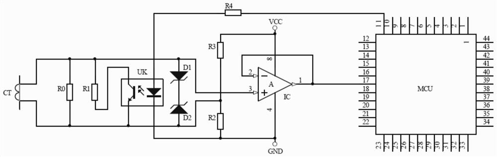
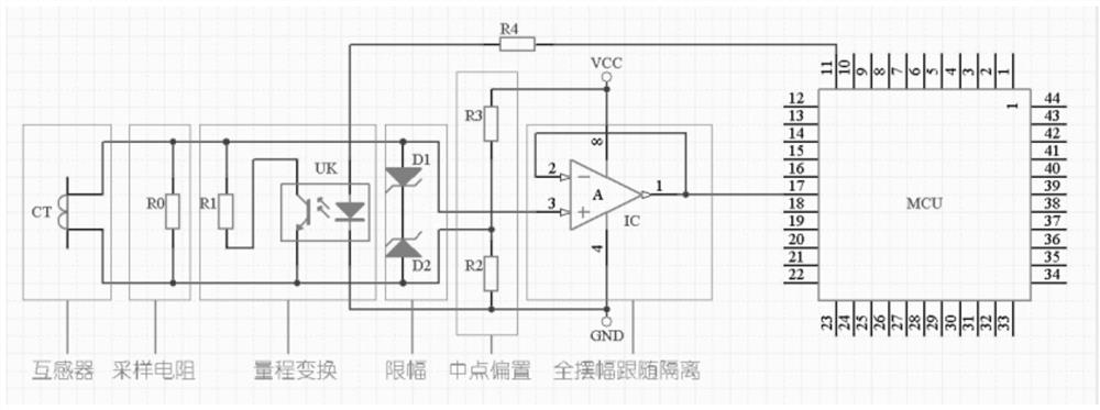
[0022] Such as Figure 1 to Figure 2 As shown, a current peak detection circuit includes a current mutual induction module, a sampling resistor R0, a midpoint bias module, a full swing following isolation module and a micro control unit module, and the current mutual induction module is connected to the Both ends of the pins of the sampling resistor R0, the midpoint bias module is connected t...


PUM


Abstract

The invention discloses a current peak value detection circuit, which comprises a current mutual induction module, a sampling resistor, a midpoint bias module, a full swing following isolation module and a micro control unit module. Both ends of the pin, the midpoint bias module is connected to the positive and negative ends of the DC power supply, the full swing follows the input positive pole of the isolation module and is electrically connected to the pin of the sampling resistor, and the full swing follows the input negative pole of the isolation module. The output end of the full-swing following isolation module is connected; the output end of the full-swing following isolation module is connected to the micro control unit module. In the present invention, capacitive coupling is replaced by direct coupling between circuits at all levels to reduce signal transmission delay and deformation; mid-point bias is adopted, so that the collected signal can be normally transmitted in the second half of the cycle when it is powered by a single power supply and meets the requirements of the AD terminal. input requirements while circumventing the complexities of dual-supply operation and the introduced crossover distortion.

Description

technical field [0001] The invention relates to the current detection of an AC power supply, in particular to a current peak detection circuit. Background technique [0002] In the application of AC power supply, it is often necessary to detect the current status to prevent the occurrence of short circuit, open circuit, leakage, etc. In some motor control occasions, the load size of the motor is determined by detecting the current of the motor, and the operation of the motor is adjusted according to the current , to achieve automatic control. [0003] see prior art image 3 , Traditional current detection mostly uses transformers to generate current, current-voltage conversion, AC amplification and shaping, and AD conversion to produce digital signals. Among them, the unique circuit structure of AC amplification and shaping will cause crossover distortion and delay of current signals, which is extremely unfavorable for use in occasions that require accuracy and real-time pe...

Claims


Application Information

Patent Timeline
Patent Type & Authority Patents(China)
IPC IPC(8): G01R19/04G01R15/22
CPCG01R15/22G01R19/04
Inventor 张玲吴璐李玲
Owner 浙江匠联科技有限公司
Why Eureka
Try Eureka