Distance measurement binocular telescope optical system

A technology for binoculars and an optical system, applied in the optical field, can solve the problems of unfavorable product installation and adjustment, product stability, increase product volume, uncompact structure, etc., to ensure optical performance indicators, improve stability, and facilitate installation tuning effect

Pending Publication Date: 2019-09-27
刘云坤
View PDF0 Cites 3 Cited by
  • Summary
  • Abstract
  • Description
  • Claims
  • Application Information

AI Technical Summary

Problems solved by technology

[0003] The present invention mainly solves the problem that the structure of the binoculars optical system in the prior art is unreasonable, which makes the structure not compact, increases the product volume, is not conducive to product assembly and product stability, and increases the cost. It provides a Optical system of range-finding binoculars

Method used


Image

  • Distance measurement binocular telescope optical system
  • Distance measurement binocular telescope optical system
  • Distance measurement binocular telescope optical system

Examples


Embodiment 1

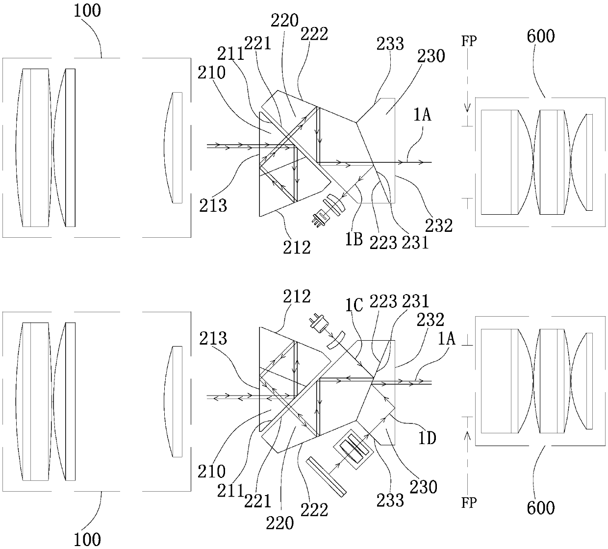
[0059] The present embodiment provides a kind of structure of ranging binoculars optical system, as figure 1 As shown, it includes an objective lens group 100 and an eyepiece lens group 600, and a mirror-symmetrical first prism group and a second prism group are arranged between the objective lens group and the eyepiece group, and each prism group corresponds to an objective lens group and an eyepiece group respectively.

[0060] The first prism group and the second prism group all comprise the first prism 220, the second prism 230 and the roof type prism 210, the roof type prism and the second prism are respectively arranged on the both sides of the first prism, the roof type prism faces the objective lens group, The second prism faces the eyepiece group, and the second prism and the first prism are glued together to form a beam splitting prism group. A laser component is arranged outside the first prism in one of the first prism group and the second prism group, and the secon...

Embodiment 2

[0082] This embodiment presents a second structure of the optical system of the range-finding binoculars. Compared with Embodiment 1, the difference lies in the arrangement of the display components. like Figure 4 As shown, the first prism group also includes a third prism 240, and the third prism includes an incident surface 241 and a third beam splitting surface 242, an angle of 22.5° is formed between the incident surface and the third beam splitting surface, and the third beam splitting surface is the same as the first prism. The reflective surfaces are glued together, the incident surface is perpendicular to the second receiving and emitting surface and the outgoing surface respectively, and the display component faces the incident surface.

[0083] The first light-splitting surface or the second light-splitting surface is coated with a light-splitting film layer, and the light-splitting film layer is:

[0084] In = 400nm-720nm, T>99%; In = 850nm - 950nm, R>99%;

[008...

Embodiment 3

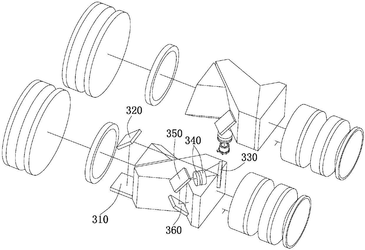
[0095] This embodiment presents a third structure of the optical system of the range-finding binoculars. Compared with Embodiment 1, the difference lies in the arrangement of the display components. like Figure 7 As shown, the display assembly includes a self-illuminating OLED display 310, a first plane reflector 320, and a first focusing lens 340. The self-illuminating OLED display is arranged between the eyepiece group and the second prism near the second prism, and automatically The light-emitting OLED display is located on the side of the second prism close to the second splitting surface, the display surface of the self-luminous OLED display is perpendicular to the exit surface, and the first plane reflector is arranged on the side opposite to the exit surface of the second prism near the third transceiver surface. In front of the side, the first plane reflector is opposite to the self-luminous OLED display, the first focusing lens is arranged between the first plane ref...


PUM


Abstract

The invention discloses a distance measurement binocular telescope optical system, which solves the problems that the optical system in the prior art is unreasonable in structure, increases the volume of a product, is not beneficial to product adjustment and product stability, and increases the cost. The system comprises an objective lens group and an eyepiece group, wherein a first prism group and a second prism group which are in mirror symmetry are arranged between the objective lens group and the eyepiece group; the first prism group and the second prism group comprise first prisms, second prisms and roof-shaped prisms; the roof-shaped prisms and the second prisms are respectively arranged on two sides of the first prisms; the roof-shaped prisms face the objective lens group; the second prisms face the eyepiece group; the second prisms are glued with the first prisms to form a beam splitting prism group; and a display component is arranged on the outer side of the beam splitting prism group. The distance measurement binocular telescope optical system is compact in structure, is beneficial to the spatial arrangement of the light path structure, reduces the volume of the product and simultaneously reduces the requirements on the manufacture of the display.

Description

technical field [0001] The invention relates to the field of optical technology, in particular to an optical system of ranging binoculars. Background technique [0002] There are still some unreasonable structures in the existing range-measuring binoculars optical system, such as the projected light path of the display is too long in the prism, which not only makes the light attenuation larger, but also reduces the utilization rate of light, and reduces the focus of the display. The brightness of the image on the surface, and also makes the structure not compact, increasing the volume of the telescope. And the combination of prisms is not reasonable enough, and the number of prisms is large, which is not conducive to product assembly and product stability, and also increases the cost. Contents of the invention [0003] The present invention mainly solves the problem that the structure of the binoculars optical system in the prior art is unreasonable, which makes the struc...

Claims


Application Information

Patent Timeline
Patent Type & Authority Applications(China)
IPC IPC(8): G02B23/02G02B23/04G02B1/10G02B5/04
CPCG02B1/10G02B5/04G02B23/02G02B23/04
Inventor 刘云坤
Owner 刘云坤
Why Eureka
Try Eureka