Skeleton Line Extraction Method Based on Projection Matching Group
A projection matching and extraction method technology, applied in the field of computer vision, can solve the problems of poor universality, long time consumption, poor positioning effect, etc. Effect
- Summary
- Abstract
- Description
- Claims
- Application Information
AI Technical Summary
Problems solved by technology
Method used
Image
Examples
Embodiment 1
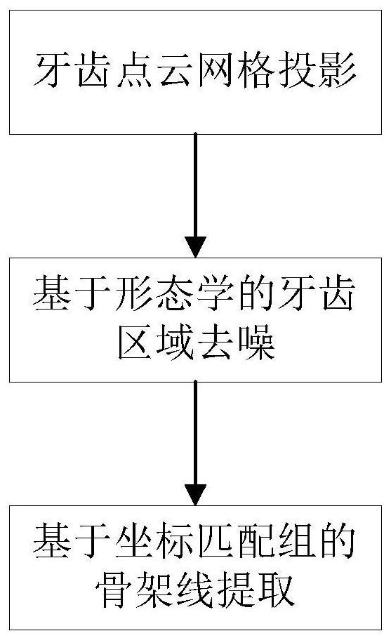
[0059] This example proposes a skeleton line extraction method based on projection matching group, using grid projection technology to map the tooth point cloud to a two-dimensional plane, and then using morphological operations to denoise to obtain tooth structure, and then using coordinate matching group technology to obtain three-dimensional teeth Skeleton lines, such as figure 1 shown.
[0060]The method of this embodiment specifically includes the following steps:
[0061] 1. Tooth point cloud grid projection
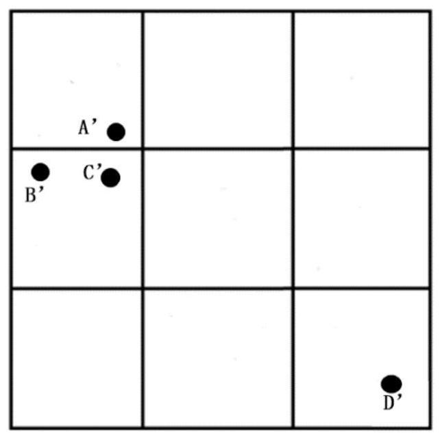
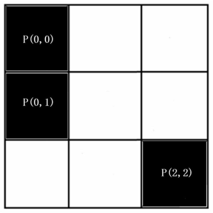
[0062] Since a jaw point cloud has tens of thousands of three-dimensional points, for the convenience of description, this embodiment only deduces a local point cloud Q of the whole. The point cloud Q consists of four points, namely:
[0063] A=(x 1 ,y 1 ,z 1 ), B=(x 2 ,y 2 ,z 2 ), C=(x 3 ,y 3 ,z 3 ), D=(x 4 ,y 4 ,z 4 ). In order to obtain the two-dimensional skeleton line, the plane where the two-dimensional skeleton line is located is the O-XY pla...
Embodiment 2
[0114] Based on the 3D skeleton line extraction method based on the projection matching group proposed in the above-mentioned embodiment 1, the method of this embodiment also includes based on the extracted 3D skeleton line, using the spatial position of the overlapping area and the skeleton line, and using the normal distance as a criterion from The overlapping regions are classified in the gingiva point cloud, as follows:
[0115] The main function of the extracted skeleton line is that since the skeleton line is in the center of the tooth point cloud, it can be used as a dividing line to distinguish the buccal gingiva and lingual gingiva by using the positive and negative normal distances, as well as the buccal gingiva line and lingual side gum line, and the buccal gum line is the anterior arch, and the buccal gum is the overlap area.
[0116] The specific process of extracting the anterior dental arch using the skeleton line is as follows:
[0117] Let the extracted skele...
Embodiment 3
[0124]In this embodiment, the skeleton line extraction algorithm based on projection matching group in the above-mentioned embodiment 1 is compared with the existing iterative refinement algorithm based on Laplacian operator; the experimental results given in this embodiment are all based on the Matlab experimental environment, It runs on a PC with CPUIntel(R)Core(TM)i3-6100@3.70GHz and 8G memory, and the operating system is Windows 64-bit operating system. For the same jaw point cloud, under different sampling conditions, the number of different point clouds and the number of triangle meshes (jaw 1: vertices: 19601, faces: 38084; jaw 2: vertices: 13865, faces: 26277; jaw 3: Vertices: 10557x3, faces: 19816x3; Jaw 4: vertices: 5945, faces: 10719; Jaw 5: vertices: 1532, faces: 2698; ) to compare the effect of the algorithm. Analyze the effect of skeleton line extraction and the time-consuming algorithm under different numbers of point clouds and triangular meshes. Take jaw 1 as...
PUM
 Abstract
Description
Claims
Application Information
 - R&D
- Intellectual Property
- Life Sciences
- Materials
- Tech Scout
- Unparalleled Data Quality
- Higher Quality Content
- 60% Fewer Hallucinations
Browse by: Latest US Patents, China's latest patents, Technical Efficacy Thesaurus, Application Domain, Technology Topic, Popular Technical Reports.
© 2025 PatSnap. All rights reserved.Legal|Privacy policy|Modern Slavery Act Transparency Statement|Sitemap|About US| Contact US: help@patsnap.com


