Compound roll for rolling and method for producing same

一种制造方法、复合辊的技术,应用在轧辊、金属轧制、制造工具等方向,能够解决轴部长寿命化存有限度等问题,达到优异抗事故性、成本削减、耐磨耗性改善的效果

Active Publication Date: 2019-09-27
PROTERIAL LTD
View PDF8 Cites 0 Cited by
  • Summary
  • Abstract
  • Description
  • Claims
  • Application Information

AI Technical Summary

Problems solved by technology

Therefore, there is a limit to the longevity of the shaft

Method used


Image

  • Compound roll for rolling and method for producing same
  • Compound roll for rolling and method for producing same
  • Compound roll for rolling and method for producing same

Examples


Embodiment 1~6 and comparative example 1~4

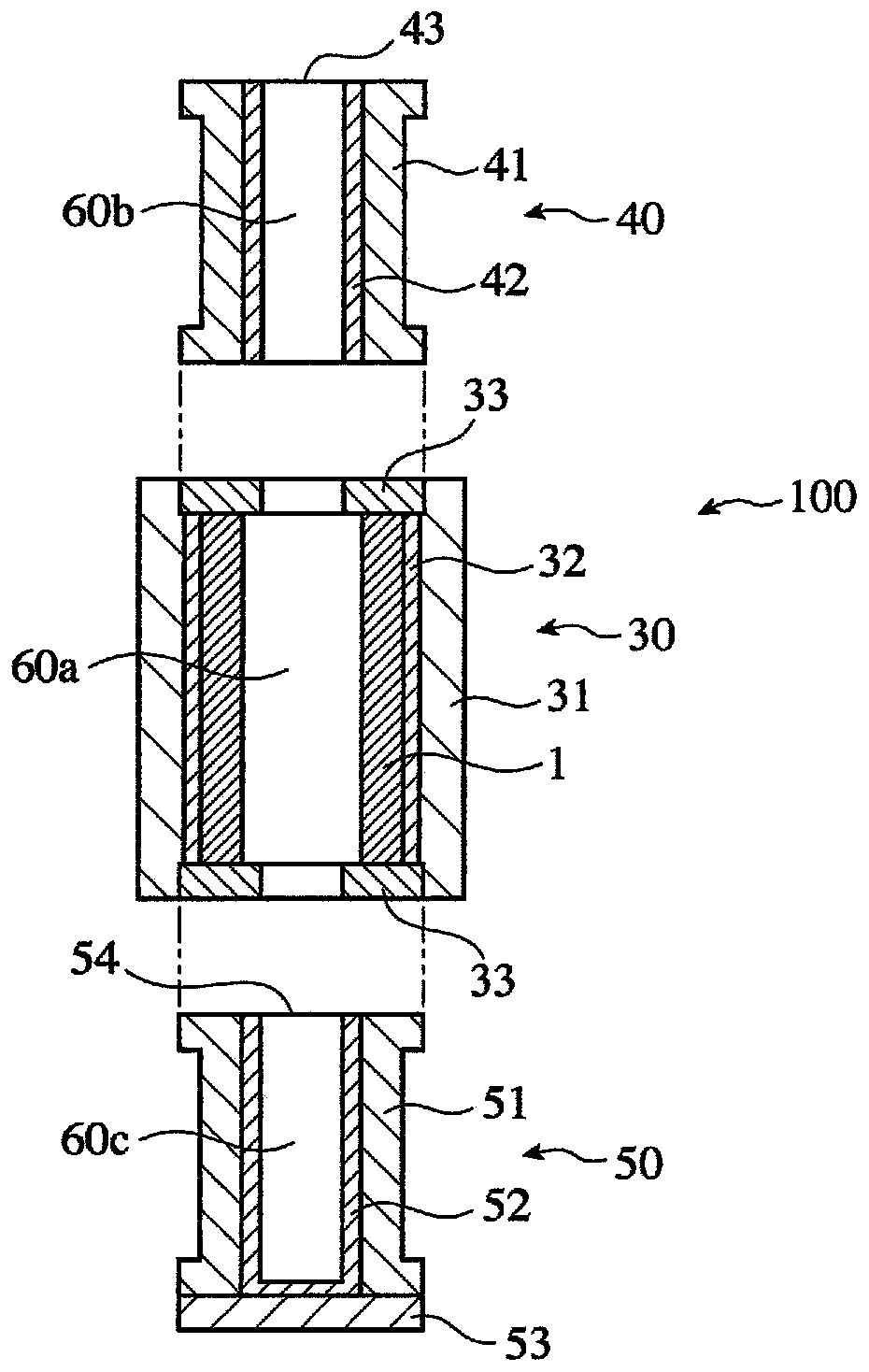
[0113] A cylindrical mold 30 (inner diameter 800 mm and length 2500 mm) of the structure shown in FIG. impurities.) of molten metal, centrifugal casting outer layer 1. An oxide-based flux mainly composed of Si was added to centrifugal casting to form a flux layer with a thickness of 5 mm on the inner surface of the outer layer. Thereafter, the cylindrical mold 30 having the outer layer 1 (thickness: 90 mm) formed on the inner surface of the mold and the flux layer (thickness: 5 mm) formed on the inner surface of the mold is erected, and the hollow space for forming the drive side shaft portion 22 is formed. A cylindrical mold 30 is erected on the lower mold 50 (inner diameter 600mm and length 1500mm), and a hollow upper mold 40 (inner diameter 600mm and length 23) is erected on the cylindrical mold 30 for forming the driven side shaft portion 23. 2000mm), constitute the static casting mold 100 shown in Fig. 3(b).

[0114] After the measurement of the radiation thermometer de...


PUM

PropertyMeasurementUnit
diameteraaaaaaaaaa

Abstract

A compound roll for rolling which: has a welded and integrated outer layer and inner layer; is configured in a manner such that the outer layer thereof comprises an Fe-based alloy containing, by mass, 1-3% C, 0.3-3% Si, 0.1-3% Mn, 0.1-5% Ni, 1-7% Cr, 1-8% Mo, 4-7% V, 0.005-0.15% N, and 0.05-0.2% B; is configured in a manner such that the inner layer thereof comprises a graphitic cast iron containing, by mass, 2.4-3.6% C, 1.5-3.5% Si, 0.1-2% Mn, 0.1-2% Ni, less than 0.7% Cr, less than 0.7% Mo, 0.05-1% V, and 0.01-0.1% Mg; has a body core section where the inner layer is welded to the outer layer, and has shaft parts that integrally extend from both ends of the body core section, wherein at least one of the shaft parts contains hard MC carbides having an equivalent circle diameter of 5 [mu]m or greater in an amount equal to or greater than 200 / cm2.

Description

technical field [0001] The present invention relates to a composite roll for rolling in which an outer layer excellent in abrasion resistance and accident resistance and an inner layer excellent in toughness and abrasion resistance are welded and integrated, and a method for manufacturing the same. Background technique [0002] As work rolls for hot rolling, centrifugally cast composite rolls in which the outer layer and the inner layer are integrated by welding are widely used. The outer layer is made of wear-resistant iron Formed from a base alloy, the inner layer is formed from tough ductile iron. In centrifugally cast composite rolls, the outer layer of the roll is damaged due to heat and mechanical loads caused by contact with the rolled material, such as abrasion and surface roughness, which cause deterioration of the surface quality of the rolled material. In addition, when the composite roll is used in the back stage of the hot finishing mill, when the rolled materi...

Claims


Application Information

Patent Timeline
Patent Type & Authority Applications(China)
IPC IPC(8): B21B27/00B22D13/02B22D19/16C22C37/00
CPCB21B27/00B22D13/02B22D19/16C22C37/00C22C37/04C22C37/08C22C37/10B32B15/011B21B2203/18B21B27/03B22D11/008
Inventor 野崎泰则小田望服部敏幸
Owner PROTERIAL LTD
Why Eureka
Try Eureka