Segmented optical system for a lighting module for angle-resolved illumination

A lighting module and optical element technology, applied in optics, optical elements, microscopes, etc., can solve the problems of uncontrolled orientation of the sample area, limited light efficiency in the sample area, and high cost

Inactive Publication Date: 2019-09-27
CARL ZEISS MICROSCOPY GMBH
View PDF11 Cites 1 Cited by
  • Summary
  • Abstract
  • Description
  • Claims
  • Application Information

AI Technical Summary

Problems solved by technology

Especially in cases where large angles are used between different optical paths, a common optical system can be cost prohibitive
If the optics were not used at all, this could lead to an uncontrolled orientation of the sample area; additionally, the light efficiency in the sample area would be limited

Method used


Image

  • Segmented optical system for a lighting module for angle-resolved illumination
  • Segmented optical system for a lighting module for angle-resolved illumination
  • Segmented optical system for a lighting module for angle-resolved illumination

Examples


Embodiment Construction

[0098] The characteristics, features and advantages of the present invention described above and the manners and methods for realizing these characteristics, features and advantages will become clearer and clearer in combination with the following description of the embodiments, which will be described in detail in conjunction with the accompanying drawings.

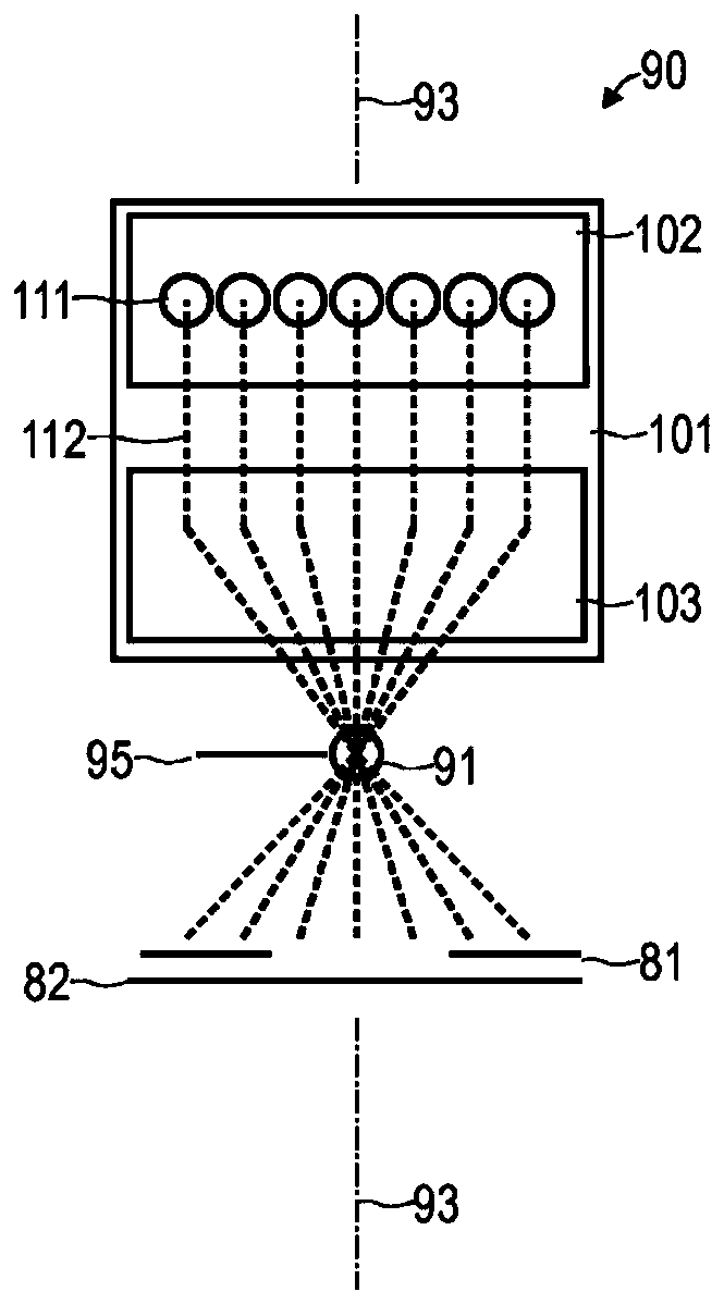
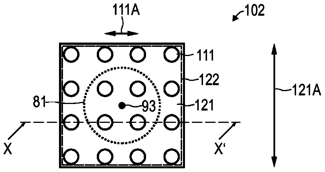
[0099] The invention is explained in more detail below with reference to preferred embodiments and with reference to the drawings. In the figures the same reference numbers designate the same or similar elements. The figures represent schematically different embodiments of the invention. Elements shown in the figures are not necessarily shown to scale. More precisely, the different elements shown in the figures are shown in such a way that their function and main purpose can be easily understood by a skilled person. The connections or couplings shown in the figures between functional units and elements can also be real...


PUM


Abstract

A lighting module (101) for an optical device comprises a light source unit (102) designed to emit light along one of a plurality of beam paths (112). The lighting model (101) also comprises a plurality of laterally offset optical elements (201-203), each optical element (201-203) of the plurality of optical elements (201-203) being designed to transform at least one respective beam path (112) from the plurality of optical elements.

Description

technical field [0001] Various embodiments of the invention generally relate to a lighting module for an optical device. The lighting module can be provided, for example, for selectable angular lighting from different lighting directions. According to various examples, the lighting module comprises, in particular, a plurality of optical elements which are each provided for varying at least one corresponding beam path. Background technique [0002] Known from DE 10 2014 112 242 A1 are techniques for illuminating a sample from different illumination directions (angle-selectable illumination or structured illumination or angularly resolved illumination). By combining the images acquired for different illumination directions, a resulting image can be determined, for example with phase contrast. Phase-contrast imaging is thus possible by means of digital post-processing with selectable angles of illumination. [0003] A technique involving angle-resolved illumination is also...

Claims


Application Information

Patent Timeline
Patent Type & Authority Applications(China)
IPC IPC(8): G02B21/10G02B21/12G02B26/08
CPCG02B21/10G02B21/125G02B26/0883G02B3/0006G02B5/045G02B21/088
Inventor 拉尔斯·施托佩马提亚·希伦布兰德乌维·沃尔夫格哈德·克拉姆佩尔特
Owner CARL ZEISS MICROSCOPY GMBH
Why Eureka
Try Eureka