Shifting machine suitable for multiple poses of human body

A lift, multi-position technology, applied in the field of lift, can solve the problems of inconvenient operation, many consumables, poor self stability, etc., to achieve the effect of easy operation

Active Publication Date: 2019-10-01
NANJING KANGNI MECHANICAL & ELECTRICAL
View PDF12 Cites 4 Cited by
  • Summary
  • Abstract
  • Description
  • Claims
  • Application Information

AI Technical Summary

Problems solved by technology

[0003] Therefore, the lifting method of the existing human body lift is single-point suspension, which acts on the lifting object at one point. As long as the center of gravity of the lifting object does not coincide with the vertical line of the suspension point, shaking will occur. Therefore, shaking of the lifting object is normal and needs to be operated. The operator stabilizes the lifting object, thus increasing the difficulty of operation
At the same time, the shaking of the human body during the movement will cause discomfort to the displaced human body.
[0004] In addition, the single-point suspension focuses on one point, so the lifting surface is small, and the hoisted human body is in a curled up state. The human body curled up in the sling may cause secondary injuries during the displacement process, especially for postoperative patients.
However, the human body displacement that requires a large lifting surface, such as lying flat or reclining, cannot be realized with the existing single-point suspension lift, so its use is greatly restricted, for example, it cannot be used for paralyzed patients or ICU patients. It is also impossible to use it in some daily nursing work of bedridden patients.
[0005] In addition, because the lifting process of existing lifts is not simply up and down movement, but also includes horizontal movement, so the lifting of the human body must be accurately positioned, and the operator needs to have certain experience, otherwise

Method used


Image

  • Shifting machine suitable for multiple poses of human body
  • Shifting machine suitable for multiple poses of human body
  • Shifting machine suitable for multiple poses of human body

Examples


Embodiment 1

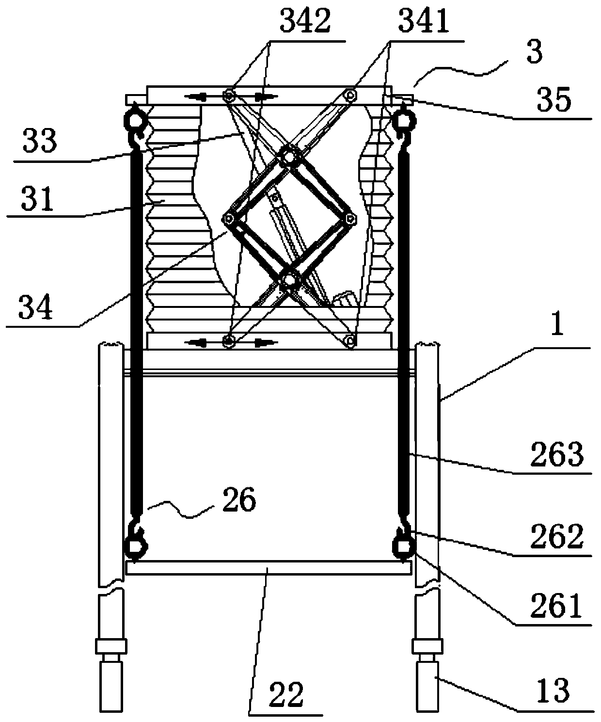
[0053] Such as figure 1 , the human body lifting machine of this embodiment is mainly composed of a mobile frame 1, a scissor lifting mechanism 3, a sling 22 and a sling 26 for carrying a human body.

[0054] The bottom of the mobile frame 1 is provided with castors 13, so that it can be moved more easily. The scissor lift mechanism 3 is arranged on the mobile frame 1 and mainly consists of a scissor lift support 34 and an electric push rod 33 . The lower end of the scissor lift bracket 34 of the present embodiment is the connection end, and the lower end is arranged on the mobile frame 1, and one end of the electric push rod 33 is connected to the scissor lift bracket 34, and the expansion and contraction of the electric push rod makes the upper end of the scissor lift mechanism 3 Lifting occurs, thereby forming a lifting end surface of the lifting end, which is presented in the entity as a lifting end panel 35 arranged on the upper end of the scissor lifting bracket 34 . T...

Embodiment 2

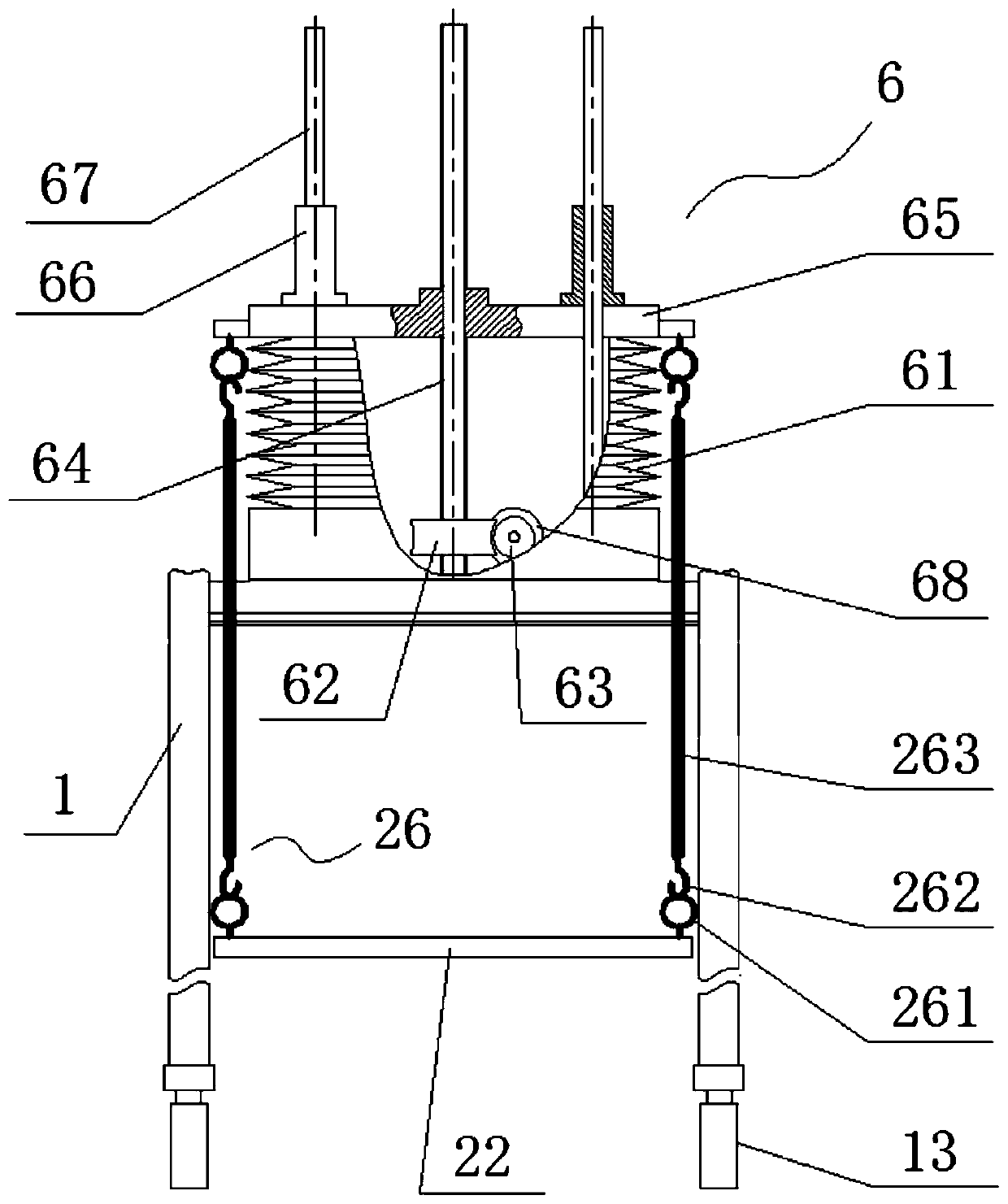
[0058] Such as image 3 , the human body shifting machine of this embodiment is mainly composed of a mobile frame 1, a scissor lift mechanism 3, a sling 22 for carrying a human body, and a sling 26. On the basis of Embodiment 1, the scissor lift mechanism 6 is used to replace the scissor lift mechanism Lifting mechanism.

[0059] Spiral lifting mechanism 6 mainly is made up of screw rod 64, nut 69, turbine 62, worm screw 63, guide rod 67 and guide sleeve 66. The screw rod 64 is rotatably vertically supported on the mobile frame 1, on which a worm gear 62 is connected, and the worm screw 63 is connected on the rotating shaft of the motor 68 and engages the transmission worm gear 62 to make the screw rod rotate. The nut 69 is arranged on the lifting end panel 65, and is composed of a threaded hole designed in the center of the lifting end panel 6. The threaded hole is matched with the screw rod 64. When the screw rod 64 rotates, the lifting end panel is made to rotate through t...

Embodiment 3

[0063] Such as Figure 4 , the body shifting machine of this embodiment is mainly composed of a mobile frame 1, a scissor lifting mechanism 3, a sling 22 for carrying a human body, a sling 26 and a suspension. On the basis of Embodiment 1, a suspension is added. Suspension is the plane frame 21A, and the included plane is much larger than the lifting end face, and it is connected to the lifting end panel 35 that appears as a lifting end face entity, so that the spreader 22 with a larger lifting plane can be hoisted.

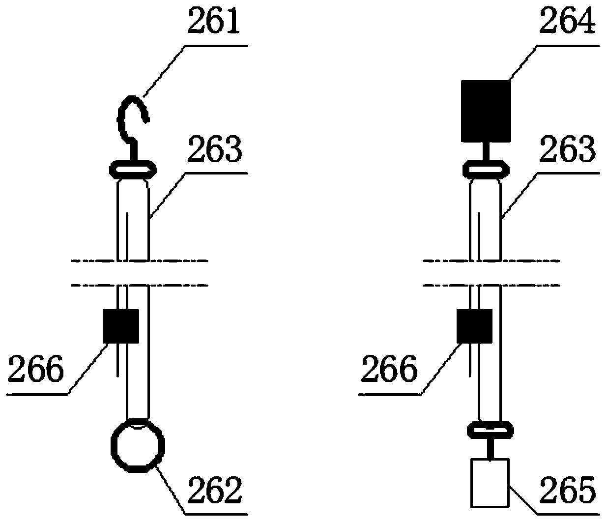
[0064] The planar frame 21A is respectively provided with installation grooves 213 along the sides, and a slider 210 is placed in the installation grooves 213 which can slide along the installation grooves, and the connecting piece is connected to the slider 265 . Such as Figure 5 , 6 , the situation of the connector 264 and the suspension ring 261 on the slider 210 respectively. Through the sliding of the slider in the installation groove, the corresponding ...


PUM


Abstract

The invention relates to a shifting machine suitable for multiple poses of a human body. The machine comprises a mobile rack, a lifting mechanism which is arranged on the mobile rack and has a vertical lifting end face, a sling bearing the human body and multiple suspenders making the sling connected to the lifting end face of the lifting mechanism, and the sling performs vertical lifting movementalong with rising and falling of the lifting mechanism. Accordingly, the human body needing to be shifted is hoisted through the lifting mechanism with the vertical lifting end face, multiple parallel slinging points together act on the sling, the human body in the shifting process cannot shake, the shifting center of gravity is located on the bearing surface formed by the mobile rack all the time, the human body moving is very stable, and operators do not need to perform the action of stably hoisting the human body except pushing the shifting machine; meanwhile, the hoisting plane is large,the machine is suitable for shifting of the human body in various postures, especially the human body posture needing a large hoisting plane, such as stable shifting in a flat posture, and thus the machine adapts to different usage scenarios.

Description

technical field [0001] The invention belongs to the field of machinery, and in particular relates to a shifting machine adapted to multiple postures of a human body. Background technique [0002] Human body lifts currently on the market are mainly composed of a movable single rod, a lifting rod with one end hinged on the upper end of the single rod, and an electric rod connecting the single rod and the lifting rod. The expansion and contraction of the electric rod makes the swing end of the lifting rod The up and down swing of the arc track lifts the human body to be displaced through the up and down shift function of the swing end. [0003] Therefore, the lifting method of the existing human body lift is single-point suspension, which acts on the lifting object at one point. As long as the center of gravity of the lifting object does not coincide with the vertical line of the suspension point, shaking will occur. Therefore, shaking of the lifting object is normal and needs ...

Claims


Application Information

Patent Timeline
IPC IPC(8): A61G7/14
CPCA61G7/1019A61G7/1034A61G7/1046A61G7/1049A61G7/1051A61G7/1055A61G7/1059A61G7/108A61G2203/70
Inventor 金元贵吕文金彪钤亚丽
Owner NANJING KANGNI MECHANICAL & ELECTRICAL
Why Eureka
Try Eureka