
Deep hole drilling method for tiny thin-wall components

A technology for thin-walled parts and deep hole drilling, which is applied in the direction of boring/drilling, drilling/drilling equipment, metal processing equipment, etc. Problems such as eccentric drill bit breakage

Active Publication Date: 2019-10-01
苏州真懿医疗有限公司
View PDF6 Cites 4 Cited by
  • Summary
  • Abstract
  • Description
  • Claims
  • Application Information

AI Technical Summary

Problems solved by technology

[0003] In this feed mode, the drill bit will have drill chips remaining, which will lead to secondary cutting of the hole; the above G83 pecking mode advances and retreats as G0 rapid feed
This feed mode will cause drill chips to remain on the drill bit and cause secondary cutting of the drill hole, which is a key factor affecting small drilling eccentricity and drill bit breakage

Method used


Image

  • Deep hole drilling method for tiny thin-wall components
  • Deep hole drilling method for tiny thin-wall components
  • Deep hole drilling method for tiny thin-wall components

Examples


Embodiment Construction

[0026] The present invention will be further described below in conjunction with the accompanying drawings. The following examples are only used to illustrate the technical solution of the present invention more clearly, but not to limit the protection scope of the present invention.

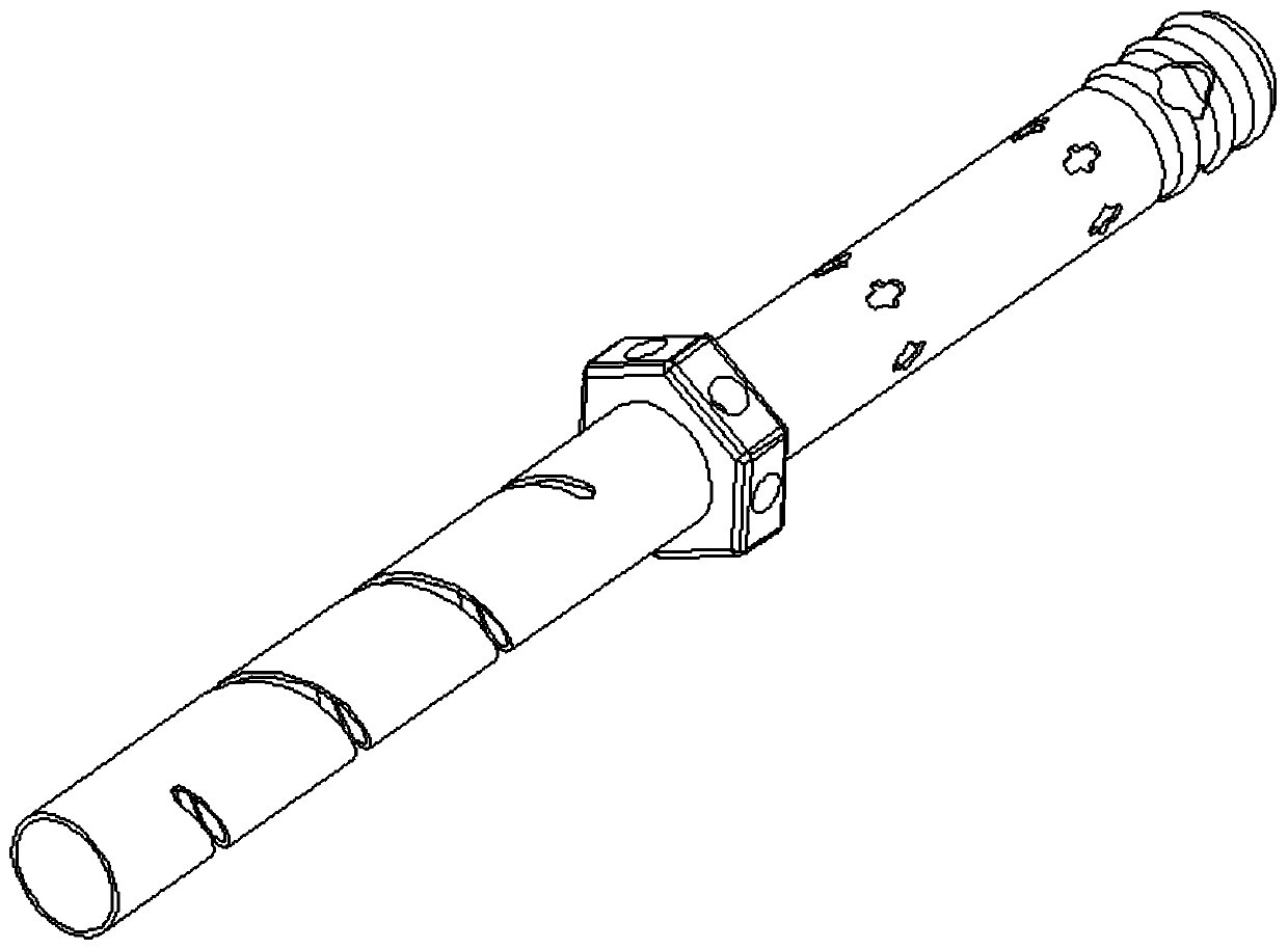
[0027] like figure 1 , figure 2 and image 3 As shown, the tiny thin-walled parts targeted by the present invention have long line diameter ratios, thin walls, and complex structures.

[0028] The present invention adopts following technical scheme: the deep hole drilling method that tiny thin-walled parts are used, it is characterized in that, comprises following 3 steps.

[0029] like Figure 7 As shown, step SS1: use the spot drill to center the product, set the drilling depth and reserve the machining allowance for the next drill bit; as a preferred embodiment, all the steps in the step SS1 The above-mentioned setting of the drilling depth specifically includes: the single feed rate o...


PUM


Abstract

The invention discloses a deep hole drilling method for tiny thin-wall components. The deep hole drilling method is characterized by comprising the following steps that in the step of SS1, a centeringdrill is utilized for centering a product, the drilling depth is set, and the machining allowance for a next drill bit is reserved; in the step of SS2, a medium drill bit is adopted for product drilling, the drilling depth is controlled, and the machining allowance for a next drill bit is reserved; and in the step of SS3, a long drill bit is adopted for product drilling, the drilling depth is controlled, and the single-side allowance is reserved. The tiny long wire diameter ratio thin-wall component drill bit machining technology is provided for the technical problems that according to existing centering drill machining, the drill bit wire diameter ratio is too long, and after a drill bit vibrates, and eccentric drilling, wall breaking and fracture are likely to happen to holes. Accordingto the technology, the technology is optimized from the aspects of tool selection, rotation speed, feeding, cutting amount and cutting reserved amount control, a drilling scrap feeding method and thelike, and accordingly the technical problems that according to tiny drill bit thin-wall deep hole drilling, eccentricity and scrap winding are likely to happen, and drill bits are prone to fracture are solved.

Description

technical field [0001] The invention relates to a deep hole drilling method for tiny thin-walled parts, belonging to the technical field of mechanical processing. Background technique [0002] like Figure 4 As shown, for the traditional drilling process, the material removal part is conical after the center drilling is used; then as Figure 5 As shown, the conical shape is reserved after the spot drilling process, which causes the force of the drill bit to suddenly increase when the hole is in contact with the material. Because the drill bit wire diameter ratio is too long, after the drill bit vibrates, the hole is very prone to drilling eccentricity, The problem of broken walls and fractures. like Image 6 Shown is a schematic diagram of the traditional tool feed, the specific CNC tool feed process is: G0X0Y0Z15T31; G0Z0.2; G83Z-7.0Q10000F0.01; 1, G83 (deep hole peck drilling); 2, Z-7.0 (drilling depth); 3, G0Z0.2 (distance from workpiece surface); 4, F (feed per revolu...

Claims


Application Information

Patent Timeline
IPC IPC(8): B23B41/02
CPCB23B41/02
Inventor 王金波孟德辉郭文平
Owner 苏州真懿医疗有限公司
Learn More