Slot turning device for part machining

A technology of parts processing and equipment, applied in the field of lathe equipment for parts processing, can solve the problems of difficult feeding structure, and achieve the effect of slowing down the impact force and avoiding damage

Inactive Publication Date: 2019-10-01
重庆宏生机电有限责任公司
View PDF11 Cites 2 Cited by
  • Summary
  • Abstract
  • Description
  • Claims
  • Application Information

AI Technical Summary

Problems solved by technology

Since the groove structure requires a certain amount of time, the screw needs to be conveyed intermittently. Due to the small size of the scr

Method used


Image

  • Slot turning device for part machining
  • Slot turning device for part machining
  • Slot turning device for part machining

Examples


Embodiment 1

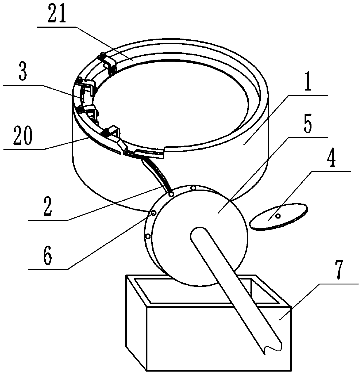
[0033] Such as figure 1 with figure 2 As shown, the lathe equipment for parts processing includes a lathe. The lathe is provided with a feeding structure and a lathe structure. The feeding structure includes a vibrating plate 1 installed on the lathe and a feed rail 2 fixed on the lathe. The vibrating plate 1. A vibrator is fixed at the lower end, the model of the vibrator is: MVE, and the vibrator is connected to an external power supply. The vibrating plate 1 is provided with a guide piece 21 in the shape of a bolt rising, and the side wall of the vibrating plate 1 is located above the guide plate 21 and is provided with a sorting groove 20. The end of the guide piece 21 close to the sorting groove 20 is inclined downward. A straightening wire 3 for correcting the screw is fixed on the top, and a screen opening is also arranged on the deflector 21. The straightening wire 3 is located on one side of the screen opening, and the other side of the screen opening communicates w...

Embodiment 2

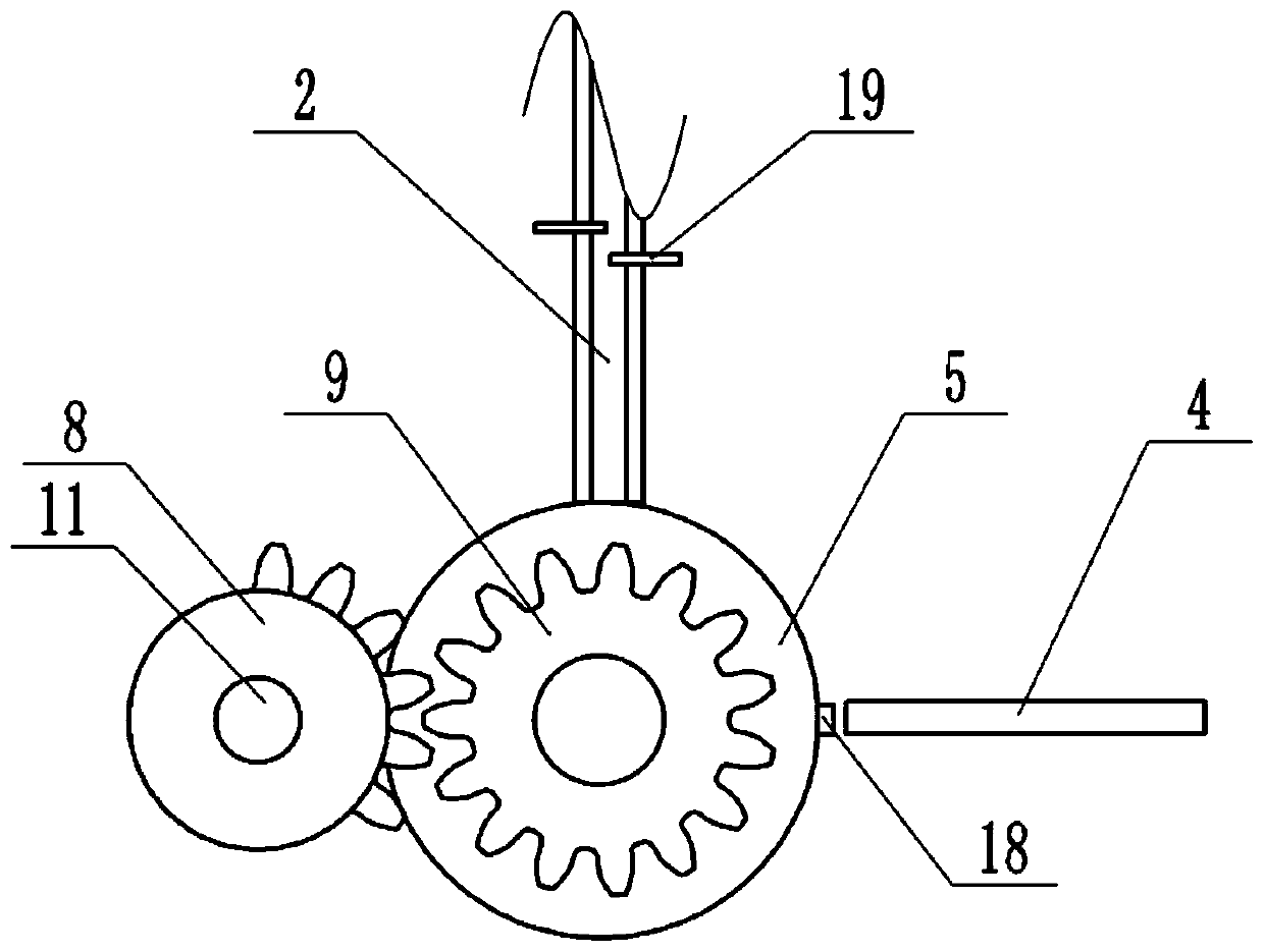
[0041] combine Figure 4 As shown, in this embodiment, on the basis of Embodiment 1, the vehicle tank structure also includes a dust collection box 12 and a dust collection cover, one end of the dust collection cover communicates with the dust collection box 12, and the other end of the dust collection cover is fixed on the block 18 , the opening of the dust cover faces the milling cutter 4. Cam 10 is also fixed on rotating shaft 11, and cam 10 outer wall is provided with cam groove, and connecting rod 14 is slidably connected in the cam groove, and piston 13 is slidably connected in dust collection box 12, and connecting rod 14 runs through and stretches in the dust collection box 12 and And the piston 13 is fixed.

[0042] The dust collecting box 12 is provided with an air inlet and an air outlet, and an air inlet check valve is installed in the air inlet. An air outlet one-way valve is installed in the air outlet, when the air pressure in the dust collection box 12 rises,...


PUM


Abstract

The invention belongs to the technical field of turning machining, and particularly discloses a slot turning device for part machining. The device comprises a lathe, a feeding structure and a slot turning structure are arranged on the lathe, the feeding structure comprises a vibration disc, a feeding rail and a conveying disc rotatably connected to the lower end of the feeding rail, the vibrationdisc communicates with an inlet of the feeding rail, a retaining needle is in sliding connection to the feeding rail transversely, multiple through holes are formed in the outer wall of the conveyingdisc in the circumferential direction, the through holes can communicate with an outlet of the feeding rail, a driving part used for driving the conveying disc to intermittently rotate is further included, the slot turning structure comprises a clamping block fixed to the lathe and a slot milling knife rotatably connected to the lathe, the clamping block is attached to the outer wall of the conveying disc, and the slot milling knife and the clamping block are located on the same height. Through the scheme, the needs of screw intermittent feeding and slot turning can be met.

Description

technical field [0001] The invention belongs to the technical field of turning processing, and in particular relates to a turning groove equipment for part processing. Background technique [0002] In the prior art, the screw processing process includes cold heading, thread rolling, grooving, polishing, screening, heat treatment, surface treatment, packaging, etc., wherein grooving refers to processing a slot or a cross groove on the head of the screw, turning Grooving is generally performed on a lathe. Existing lathes include a groove structure, and the screws are delivered to the groove structure, and the groove structure can groove on the screws. Since the groove structure requires a certain amount of time, the screw needs to be conveyed intermittently. Due to the small size of the screw, it is necessary to separate the screw for transmission during mass processing. The existing feeding structure is difficult to do. arrive. Contents of the invention [0003] The obje...

Claims


Application Information

Patent Timeline
IPC IPC(8): B23C3/30B23Q7/18B23Q7/10B23Q11/00
CPCB23C3/30B23Q7/10B23Q7/18B23Q11/0046
Inventor 贺蓓贺虹生
Owner 重庆宏生机电有限责任公司
Why Eureka
Try Eureka