A welding combined turntable device and a vacuum chamber using it

A vacuum chamber and turntable technology, used in welding equipment, auxiliary devices, auxiliary welding equipment, etc., can solve the problems of unstable welding quality, hidden quality problems, inconsistent operation process, etc., to meet the requirements of safety and reliability, and realize automatic Efficient welding production, improved stability and consistency

Active Publication Date: 2021-03-02
AECC AVIATION POWER CO LTD
View PDF8 Cites 2 Cited by
  • Summary
  • Abstract
  • Description
  • Claims
  • Application Information

AI Technical Summary

Problems solved by technology

[0002] At present, the welding of the blade damping table of the aero-engine with large bypass ratio is carried out manually by lifting the workpiece into the high-frequency induction coil in the vacuum argon chamber to complete the welding work, which is a kind of operation that depends on the skills of the operator The operation method is inconsistent due to the influence of human factors, the welding position of the blade is not uniform, resulting in uneven welding temperature, unstable welding quality, and it is easy to cause the blade to touch the induction coil to generate discharge and damage the blade body, and the blade with electric damage is installed After the engine is installed, it will cause major quality hazards; therefore, it is urgent to invent a welding device suitable for welding large fan rotor blades

Method used


Image

  • A welding combined turntable device and a vacuum chamber using it
  • A welding combined turntable device and a vacuum chamber using it
  • A welding combined turntable device and a vacuum chamber using it

Examples


Embodiment Construction

[0029] The present invention will be further described in detail below in conjunction with specific embodiments, which are to explain rather than limit the present invention.

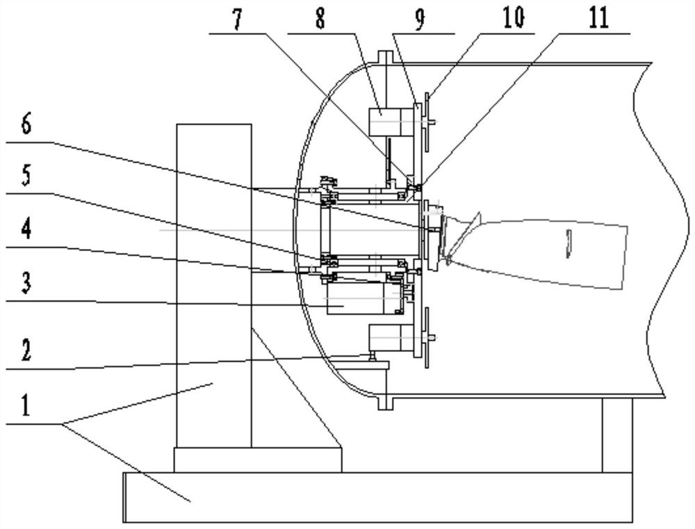
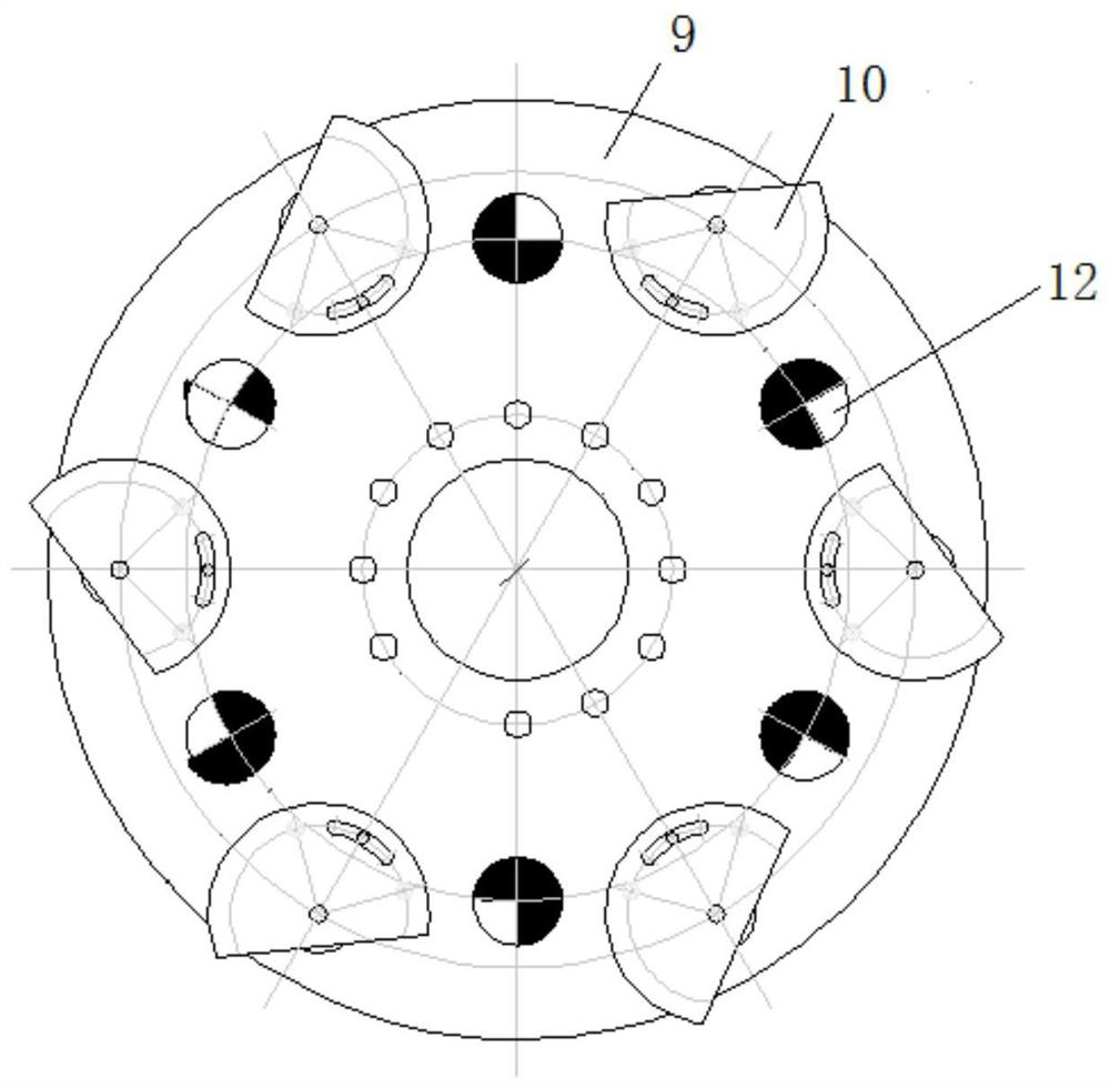
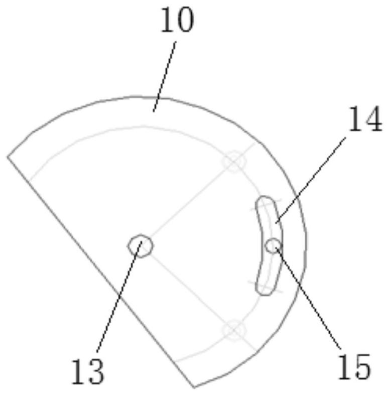
[0030] like figure 1 As shown, a welding combined turntable device of the present invention includes a large turntable 9, a small turntable 10, a rotating shaft 11, a first motor 3, a second motor 8 and a first transmission mechanism, and one end of the rotating shaft 11 is fixed to the large turntable 9. The other end is fixed with external equipment, the small turntable 10 is provided with multiple and arranged on the large turntable 9; the first motor 3 is connected with the first transmission mechanism, and the rotating shaft 11 is driven by the first transmission mechanism to rotate; The second motor 8 is arranged at a position below the large turntable 9 corresponding to each small turntable 10 to drive the small turntable 10 to rotate, and each small turntable 10 is provided with a clamp 6 for cl...


PUM


Abstract

The invention discloses a combined rotary table welding device and a vacuum chamber adopting the combined rotary table welding device. The vacuum chamber is fixedly installed on a base, the combined rotary table welding device is installed in a cavity of the vacuum chamber and comprises a large rotary table, small rotary tables, a rotating shaft, a first motor, a second motor and a first driving mechanism, one end of the rotating shaft is fixedly connected with the large rotary table, the other end of the rotating shaft is connected with the base, a plurality of small rotary tables are arranged on the large rotary table, the first motor is connected with the first driving mechanism, the rotating shaft is driven to do a rotary motion by the first driving mechanism, the second motor is arranged below the large rotary table in the mode of corresponding to each small rotary table and is used for driving the small rotary table to rotate, fixtures which are used for clamping workpieces are arranged on each small rotary table, and both the first motor and the second motor are controlled to drive by a PLC (Programmable Logic Controller) control unit. The large rotary table and the small rotary tables are combined to rotate, so that a to-be-welded damping table is sent to the combined rotary table welding device of an induction coil, manual operation is replaced by a mechanical device so as to complete the welding process, and the product quality is increased.

Description

technical field [0001] The invention relates to the field of aero-engine blade manufacturing, in particular to a welding combined turntable device and a vacuum chamber using the same. Background technique [0002] At present, the welding of the large bypass ratio aero-engine blade damping table is performed by manually lifting the workpiece into the high-frequency induction coil in the vacuum argon-filled chamber. Operation mode, due to the influence of human factors, the operation process is inconsistent, the welding position of the blade is not uniform, the welding temperature is not uniform, the welding quality is unstable, and it is easy for the blade to touch the induction coil and cause discharge to damage the blade body. After the engine is turned on, it will cause a major quality risk; therefore, it is urgent to invent a welding device suitable for welding large fan rotor blades. SUMMARY OF THE INVENTION [0003] The purpose of the present invention is to provide ...

Claims


Application Information

Patent Timeline
Patent Type & Authority Patents(China)
IPC IPC(8): B23K37/00B23K37/04
CPCB23K37/00B23K37/04B23K37/0461
Inventor 石军蔡小龙呼新岗梁养民贺振宇高军平于继平王炜
Owner AECC AVIATION POWER CO LTD
Why Eureka
Try Eureka