Air conditioning unit for EMU multiple unit train

A technology for air-conditioning units and EMUs, which is applied in railway car body parts, railway vehicle heating/cooling, transportation and packaging, etc., can solve the problems of unfavorable modification, the need for mold opening, and high cost, and can reduce weight and eliminate mold opening. Cost, cycle time reduction and cost effectiveness

Active Publication Date: 2019-10-01
石家庄国祥运输设备有限公司
View PDF7 Cites 5 Cited by
  • Summary
  • Abstract
  • Description
  • Claims
  • Application Information

AI Technical Summary

Problems solved by technology

[0006] The present invention aims at the technical problems in the prior art that the sealing flange is a profile structure that requires mold opening, high cost and is not conducive to modification, and provides an air conditioning unit for EMU EMUs, by designing the sealing flange as a sheet metal part , to achieve the purpose of simplifying the structure and reducing the cost while ensuring the sealing

Method used


Image

  • Air conditioning unit for EMU multiple unit train
  • Air conditioning unit for EMU multiple unit train
  • Air conditioning unit for EMU multiple unit train

Examples


Embodiment 1

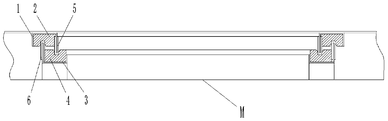
[0030] In this embodiment, the first sealing assembly includes a first annular sealing flange 1 arranged at the outer edge of the tuyere and a first sealing rubber strip 2 arranged in the annular groove of the first annular sealing flange 1 . Through the installation of the air-conditioning unit and the top of the compartment, the first sealing rubber strip 2 is closely attached to the top of the compartment to achieve sealing.

[0031] See attached Image 6 , the above-mentioned first annular sealing flange 1 is formed by a bending process, which saves the mold opening cost of the mold, and is also conducive to the modification of the design scheme. The bent annular groove facilitates the installation of the sealing strip.

Embodiment 2

[0033] Different from Embodiment 1, the first seal between the air outlet and the roof of the compartment can be realized through the first sealing assembly. Further, a second sealing assembly forming a second seal is also provided between the top of the compartment and the above-mentioned tuyere. The second sealing assembly includes a second annular sealing flange 3 arranged on the top of the compartment and a second annular sealing flange arranged on the second annular sealing flange. The second sealing strip 4 in the annular groove of 3.

[0034] The second annular sealing flange 3 is the same as the first annular sealing flange 1 and is formed by bending process, the difference lies in the height and size of the inner and outer edges.

[0035] The height of the inner annular edge of the above-mentioned first annular sealing flange 1 is greater than the height of the outer annular edge and extends into the groove of the second sealing strip 4 to compress the bottom of the g...


PUM


Abstract

The invention discloses an air conditioning unit for an EMU multiple unit train and belongs to the technical field of air conditioning equipment of rail vehicles. The air conditioning unit comprises an air conditioning unit body which is characterized in that a first sealing assembly is arranged between an air port in the bottom of the air conditioning unit body and the top of a car; the first sealing assembly comprises a first annular sealing flange arranged at the outer edge of the air port and a first sealing rubber strip arranged in an annular groove of the first annular sealing flange. The air conditioning unit disclosed by the invention has the beneficial effects that 1, the sealing flange at the air port and the car is a bended formed metal sheet part, so that an existing section bar is replaced and a die opening cost is cancelled while the sealing effect is guaranteed, and meanwhile, a design scheme is modified favorably, and the design cost and the product cost are reduced greatly; and 2, the air port and the car are of a double-layered sealing structure, and meanwhile, the double-layered sealing structure is of a labyrinth seal, so that the sealing property of the positions of the air ports is guaranteed, and the airtightness of the unit is achieved by means of a pressure wave protecting valve arranged in the unit.

Description

technical field [0001] The invention belongs to the technical field of air-conditioning equipment for rail vehicles, and in particular relates to an air-conditioning system for EMUs. Background technique [0002] EMUs are also known as Multiple Units (MU for short), and electric multiple units are called EMUs. my country's current CRH1, CRH2, CRH3, CRH5 and my country's independent intellectual property standard EMUs are all high-speed EMUs, with a maximum operating speed of 380km / h, and CRH6 at 160-250km / h. [0003] Due to the high speed of the EMU high-speed EMU, the air-conditioning unit needs to meet the requirements of light weight and good air tightness. Most of the EMU air-conditioning units adopt the aluminum alloy structure box and adopt the embedded installation method. Through the unit The surrounding mounting flanges are connected with the vehicle body. [0004] At least the following technical problems exist in the prior art: [0005] The existing sealing fla...

Claims


Application Information

Patent Timeline
Patent Type & Authority Applications(China)
IPC IPC(8): B61D27/00
CPCB61D27/0018
Inventor 孙永进赵少华
Owner 石家庄国祥运输设备有限公司
Why Eureka
Try Eureka