Synchronous swinging type rotary vane four-flapping-wing aircraft

A flapping-wing aircraft and synchronous swinging technology, applied in aircrafts, unmanned aerial vehicles, wings, etc., can solve the problems that restrict the popularization and application of flapping-wing aircraft, the overall low efficiency of flapping-wing aircraft, and the low aerodynamic efficiency. Simple structure, low production cost, and the effect of improving aerodynamic efficiency

Active Publication Date: 2019-10-01
GLOBAL INST OF SOFTWARE TECH +1
View PDF8 Cites 2 Cited by
  • Summary
  • Abstract
  • Description
  • Claims
  • Application Information

AI Technical Summary

Problems solved by technology

The main reason for the overall low efficiency of flapping wing aircraft is that most of the current research simply imitates the shape and flapping motion of the wings of birds or insects, but it is difficult to realize the use of the wing's own posture and structure in the process of flapping wings of flying creatures. The change of air resistance reduces air resistance and generates unsteady aerodynamic force, and the resulting low aerodynamic efficiency seriously restricts the popularization and application of flapping-wing aircraft

Method used


Image

  • Synchronous swinging type rotary vane four-flapping-wing aircraft
  • Synchronous swinging type rotary vane four-flapping-wing aircraft
  • Synchronous swinging type rotary vane four-flapping-wing aircraft

Examples


Embodiment 1

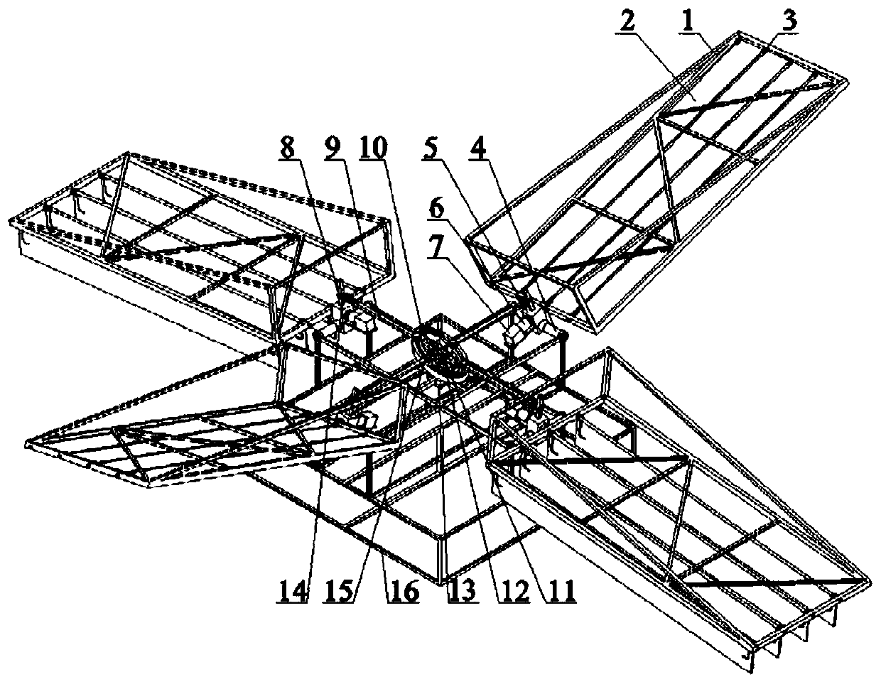
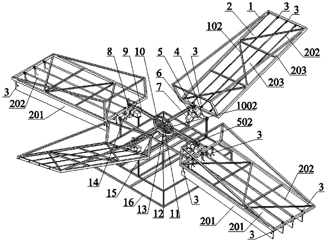
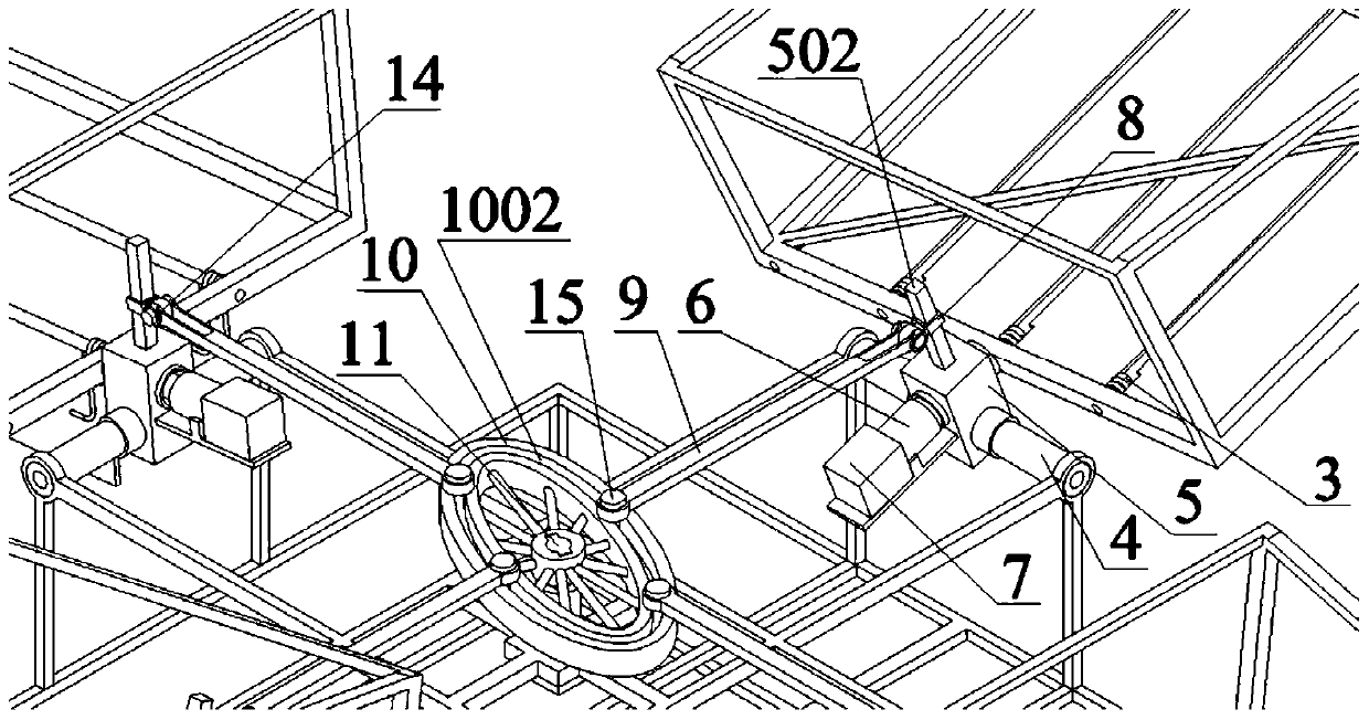
[0042] combine figure 1 , figure 2 , image 3 , Figure 4 , Figure 5 , Figure 6 , Figure 7 , Figure 8 , Figure 9 , Figure 10 and Figure 11 , a high-voltage wire inspection UAV using a synchronous swinging four-flapping wing aircraft with rotatable wings. Including flapping wing frame 1, wings 2, torsion spring 3, swing shaft 4, connector 5, first reducer 6, stepper motor 7, connecting rod 8, push rod 9, cam 10, transmission shaft 11, second Reducer 12, motor 13, first pin shaft 14, second pin shaft 15 and fuselage frame 16, wing installation hole 101, wing limit beam 102 and flapping wing rotating shaft 103 are arranged on flapping wing frame 1, and wing There are fin windward side 201, fin shaft 202 and fin leeward side 203 on 2, swing shaft hole 501, square shaft 502 and flapping wing shaft hole 503 are arranged on connector 5, the axis of swing shaft hole 501 and flapping wing shaft The axis of the hole 503 is vertical, the connecting rod square hole 801 ...

Embodiment 2

[0044] This embodiment 2 provides a special drone for high-rise fire extinguishing, its structure is the same as that of embodiment 1, the difference is: the number of fins 2 is 6, the fin limit beam 102, the strengthening vertical beam 104, the strengthening beam 105 and Reinforcing inclined beams 106 all adopt engineering plastics. It is a high-level fire-fighting special UAV using a synchronous swinging four-flapping wing aircraft with rotatable wings. Including flapping wing frame 1, wings 2, torsion spring 3, swing shaft 4, connector 5, first reducer 6, stepper motor 7, connecting rod 8, push rod 9, cam 10, transmission shaft 11, second Reducer 12, motor 13, first pin shaft 14, second pin shaft 15 and fuselage frame 16, wing installation hole 101, wing limit beam 102 and flapping wing rotating shaft 103 are arranged on flapping wing frame 1, and wing There are fin windward side 201, fin shaft 202 and fin leeward side 203 on 2, swing shaft hole 501, square shaft 502 and f...

Embodiment 3

[0046]This embodiment 3 provides an agricultural plant protection unmanned aerial vehicle, its structure is the same as that of embodiment 1, the difference is: the number of fins 2 is 8, the fin limit beam 102, the reinforcement vertical beam 104, the reinforcement beam 105 and the reinforcement Slanting beam 106 all adopts engineering plastics. An agricultural plant protection UAV using a synchronously swinging four-flapping wing aircraft with rotatable wings. Including flapping wing frame 1, wings 2, torsion spring 3, swing shaft 4, connector 5, first reducer 6, stepper motor 7, connecting rod 8, push rod 9, cam 10, transmission shaft 11, second Reducer 12, motor 13, first pin shaft 14, second pin shaft 15 and fuselage frame 16, wing installation hole 101, wing limit beam 102 and flapping wing rotating shaft 103 are arranged on flapping wing frame 1, and wing There are fin windward side 201, fin shaft 202 and fin leeward side 203 on 2, swing shaft hole 501, square shaft 50...


PUM


Abstract

The invention relates to the field of flapping wing type aircrafts and flight robots, in particular to a synchronous swinging type rotary vane four-flapping-wing aircraft. The synchronous swinging type rotary vane four-flapping-wing aircraft comprises flapping wings, swinging shafts, connecting pieces, first speed reducers, stepping motors, a transmission mechanism, a second speed reducer, a motorand a machine body frame. The four horizontal-direction swinging shafts are symmetrically installed and fixed to the periphery of the machine body frame. The four connecting pieces are connected to the four swinging shafts and oppositely rotate. The four flapping wings are connected to the four connecting pieces correspondingly and can oppositely rotate. Each flapping wing comprises a flapping wing frame and a rotary vane arranged in the flapping wing frame, wherein a torsion spring is further arranged in the flapping wing frame for vane resetting. The transmission mechanism is connected to the two connecting pieces, and after the motor is decelerated through the second speed reducer, the transmission mechanism is driven to move, the four connecting pieces synchronously swing up and down,and the four stepping motors drive the four flapping wings to rotate after being decelerated through the two first speed reducers.

Description

technical field [0001] The invention relates to the field of flapping-wing aircraft and flying robots, in particular to a synchronously swinging four-wing flapping-wing aircraft with rotatable wings. Background technique [0002] There are three flight types of aircraft flying: fixed wing, rotary wing and flapping wing. Among them, flapping wing flight is the flying mode adopted by flying creatures in nature. It mainly uses the up and down flapping of the wings to generate lift and thrust at the same time. , hovering and propulsion functions are based on one body, and at the same time have strong maneuverability and flexibility, and are more suitable for flying around obstacles. For small-sized and low-speed aircraft flying under low Reynolds numbers, the unsteady lift generated by the flapping wing is much greater than the constant lift of the fixed wing; from the perspective of thrust, the propulsion efficiency of the flapping wing is higher than that of the propeller. ...

Claims


Application Information

Patent Timeline
Patent Type & Authority Applications(China)
IPC IPC(8): B64C33/00B64C33/02B64C3/18B64C3/38B64C1/00
CPCB64C33/00B64C33/02B64C3/18B64C3/385B64C1/0009B64U2101/00
Inventor 邱明韩丽东杨帅鹏费金陵蔡伟义范丽廖振强
Owner GLOBAL INST OF SOFTWARE TECH
Why Eureka
Try Eureka