Crack monitoring sensor based on plasma spraying and its preparation and monitoring method

A technology for monitoring sensors and plasma, which is applied in the fields of instruments, coatings, melt spraying, etc., can solve the problems of complex preparation methods of crack monitoring sensors, difficulty in realizing large-scale mass production and implementation, and monitoring of cracks in dangerous parts, and achieve the The method is simple and efficient, convenient for engineering application, and solves the effect of complex preparation method.

Active Publication Date: 2021-09-03
何舒扬
View PDF7 Cites 0 Cited by
  • Summary
  • Abstract
  • Description
  • Claims
  • Application Information

AI Technical Summary

Problems solved by technology

[0008] The purpose of the present invention is to provide a crack monitoring sensor based on plasma spraying, to solve the problem of poor durability caused by the independence of the existing sensor and target monitoring structure and the crack monitoring sensor can only carry out crack detection on dangerous parts of regular shape However, it is impossible to monitor cracks in dangerous parts of arbitrary shapes.
[0009] Another object of the present invention is to provide a method for preparing a crack monitoring sensor based on plasma spraying, so as to solve the problems that the existing method for preparing a crack monitoring sensor is complex and difficult to implement in large-scale batch production
[0010] Another object of the present invention is to provide a crack monitoring method to solve the problem of crack monitoring of dangerous parts of any shape

Method used


Image

  • Crack monitoring sensor based on plasma spraying and its preparation and monitoring method
  • Crack monitoring sensor based on plasma spraying and its preparation and monitoring method
  • Crack monitoring sensor based on plasma spraying and its preparation and monitoring method

Examples


Embodiment Construction

[0047] The following will clearly and completely describe the technical solutions in the embodiments of the present invention with reference to the accompanying drawings in the embodiments of the present invention. Obviously, the described embodiments are only some, not all, embodiments of the present invention. Based on the embodiments of the present invention, all other embodiments obtained by persons of ordinary skill in the art without making creative efforts belong to the protection scope of the present invention.

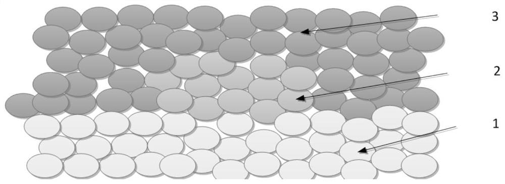
[0048] Crack monitoring sensors based on plasma spraying, such as figure 1 and Figure 3a~3c Shown is a functionally graded mosaic film structure in which the insulating base layer 1 , the damage sensing element 2 and the encapsulation protection layer 3 are integrated on the surface of the target monitoring structure by a plasma spraying method. The insulating base layer 1 is located at the bottom and combined with the surface of the target monitoring struct...


PUM

PropertyMeasurementUnit
thicknessaaaaaaaaaa
particle sizeaaaaaaaaaa
electrical resistivityaaaaaaaaaa

Abstract

The invention discloses a crack monitoring sensor based on plasma spraying and its preparation and monitoring methods. The crack monitoring sensor integrates an insulating base layer, a damage sensing element and a package protection layer in an arbitrary shape through a plasma spraying method. A functionally graded mosaic membrane structure on the surface of the target monitoring structure whose shape matches that of the crack monitoring site. The damage sensing element is a multi-ring sensing element structure, the centers of each ring overlap, the distance between two adjacent rings is equal, and each ring is provided with an output voltage lead. The plasma-sprayed crack monitoring sensor is sprayed on the crack surface of the target monitoring structure, and a constant power supply is externally connected to both ends of the crack surface through the output voltage lead of the damage sensing element, and then the potential difference between the two ends of the crack surface of the target monitoring structure is measured, and the target monitoring The functional relationship between the crack length of the structure and the potential difference determines the crack length of the target monitoring structure, and realizes the crack monitoring of dangerous parts with arbitrary shapes.

Description

technical field [0001] The invention belongs to the technical field of crack monitoring sensor preparation, in particular to a crack monitoring sensor based on plasma spraying, a preparation method thereof, and a crack monitoring method. Background technique [0002] The damage and destruction of structures under the action of changing stress (strain) is called fatigue damage or fatigue failure. Fatigue failure is the most common failure mode of equipment and components, accounting for about 50% to 90% of all component failures. Fatigue failure is usually due to the initiation and development of cracks, and the initiation and development of cracks eventually leads to the destruction of structures. Therefore, monitoring structural cracks is an important method to understand the safety status of structures. The traditional crack monitoring method or crack sensor preparation method is to detect cracks on dangerous parts with regular shapes (such as circular hole shapes, etc.), ...

Claims


Application Information

Patent Timeline
Patent Type & Authority Patents(China)
IPC IPC(8): G01N27/20C23C4/134G01B7/02
CPCC23C4/134G01B7/02
Inventor 何舒扬
Owner 何舒扬
Why Eureka
Try Eureka