Burner ring

A burner and fire cover technology, which is applied in the direction of burner, gas fuel burner, combustion method, etc., can solve problems such as blockage, main fire hole flame separation, and inability to ensure stable combustion, etc., to achieve enhanced flame stabilization, stable flame stability, Achieve self-cleaning effect

Pending Publication Date: 2019-10-01
NINGBO FOTILE KITCHEN WARE CO LTD
View PDF1 Cites 4 Cited by
  • Summary
  • Abstract
  • Description
  • Claims
  • Application Information

AI Technical Summary

Problems solved by technology

[0003] It can be seen from the above that the small flame-stabilizing hole on the existing burner fire cover is completely exposed to the outside, so that when the overflow drips to the fire cover, the liquid will flow into the small flame-stabilizing hole along the outer wall of the fire cover, and because the small flame-stabilizing hole The pore diameter is generally small, so it is easy to be blocked, which will cause the main flame hole to leave the flame and cannot guarantee stable combustion

Method used


Image

  • Burner ring
  • Burner ring
  • Burner ring

Examples


Embodiment 1

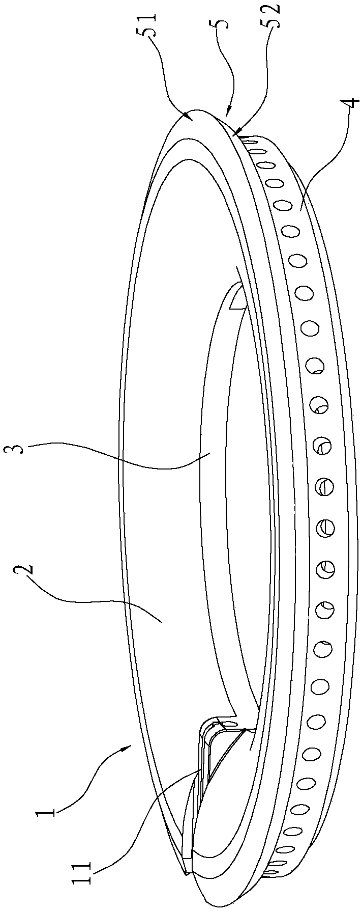
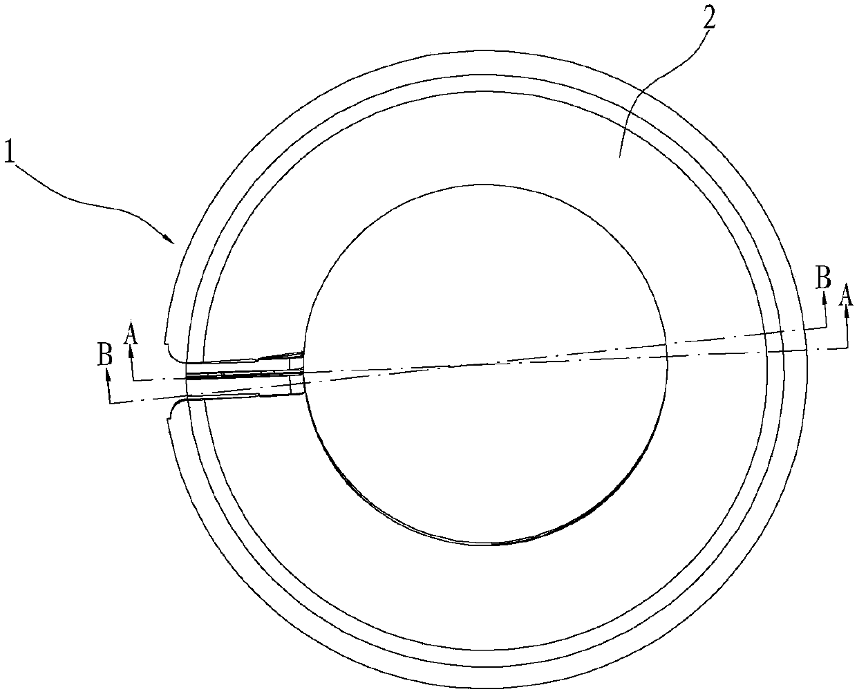
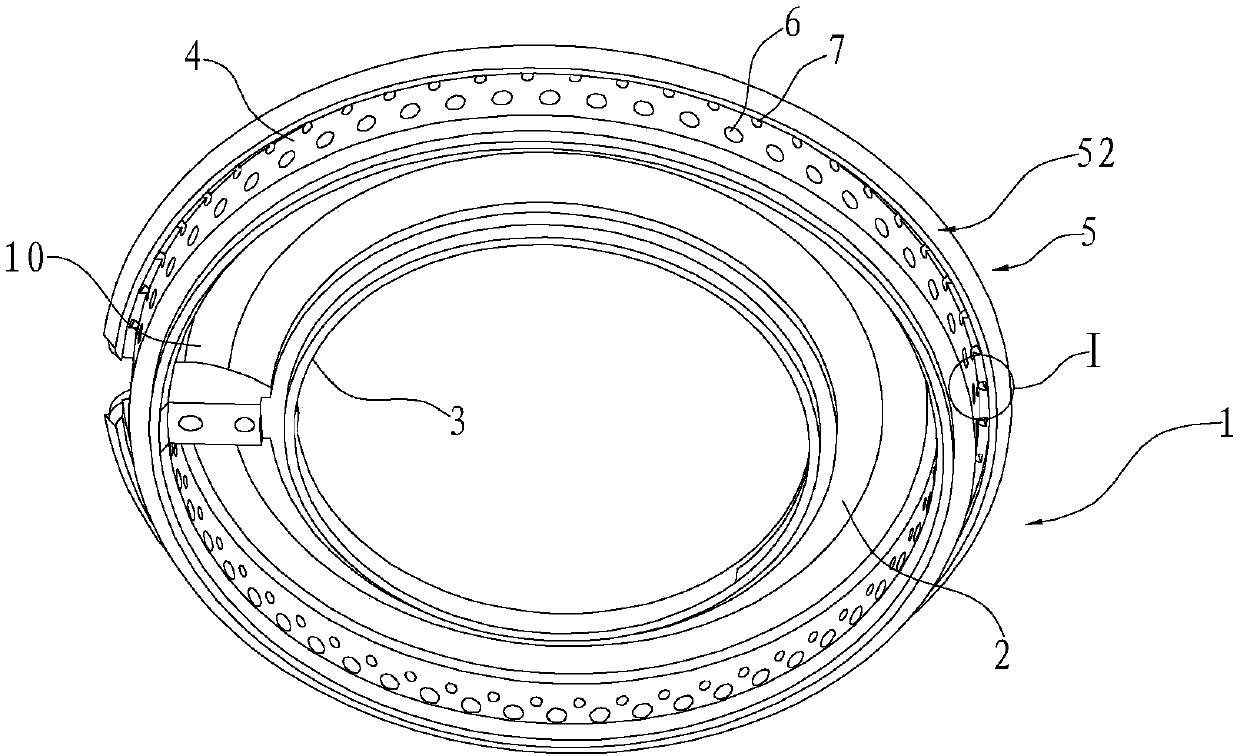
[0029] like Figures 1 to 6 As shown, a burner fire cover includes an annular fire cover body 1, the fire cover body 1 includes an annular top wall 2, inner and outer edges respectively extending vertically downward from the inner and outer edges of the top wall 2. The outer ring walls 3 and 4, wherein, the outer ring wall 4 is respectively provided with a fire outlet hole 6 and a flame stabilization hole 7 at intervals along the circumferential direction. In this embodiment, the burner fire cover is an outer ring fire cover, the holes of the fire outlet hole 6 and the flame stabilization hole 7 are inclined upward from the inside to the outside, and the hole channel of the fire outlet hole 6 and the hole channel of the flame stabilization hole 7 are parallel to each other. set up.

[0030] Further, the above-mentioned flame stabilization hole 7 is located above the fire outlet hole 6, and the flame stabilization hole 7 and the fire outlet hole 6 are arranged at intervals, so...

Embodiment 2

[0037] like Figures 7 to 9 As shown, what is different from Embodiment 1 is that in this embodiment, the inner side of the flame stabilizing eaves 5 is provided with a baffle wall 8 that can laterally separate the inner cavity of the flame stabilizing groove 50 along the circumferential direction. The adjacent baffle walls 8 The gaps therebetween form second diffuser chambers 9 , and each second diffuser chamber 9 corresponds to the flame stabilization holes 7 one-to-one. By arranging the second diffuser chamber 9, the airflow flowing out of the flame stabilization hole 7 can be diffused and reduced in speed, thereby further enhancing its flame stabilization effect. In this embodiment, the above-mentioned baffle wall 8 is arranged between the outer ring wall 4 and the flame stabilizing eaves 5 , that is, one end of the baffle wall 8 is fixed to the outer ring wall 4 , and the other end is fixed to the flame stabilizing eaves 5 .

[0038] Further, the above-mentioned baffle w...


PUM


Abstract

The invention relates to a burner ring. The burner ring comprises an annular burner ring body, wherein the burner ring body comprises a top wall, an inner ring wall and an outer ring wall, fire outletholes and flame stabilizing holes are formed in the outer ring wall in the circumferential direction, the hole channels of the flame stabilizing holes extend upwards from inside to outside along theouter ring wall, the fire outlet holes are formed below the flame stabilizing holes, the peripheral wall of the upper end of the burner ring body extends outwards in the circumferential direction to form an annular flame stabilizing blocking edge, the flame stabilizing blocking edge can shield the flame stabilizing holes from the horizontal direction, the main flame in a main fire hole is lower than the flame stabilizing edge and can be burned outwards at least along the lowest position of the flame stabilizing edge, and a flame stabilizing groove is formed between the flame stabilizing edge and the outer ring wall. According to the burner ring, the flame stabilizing edge can prevent overflow liquid from flowing into the flame stabilizing holes, the airflow speed in the flame stabilizing holes is reduced, the flame is more stable, so that the flame stabilizing effect is better, the main flame in the main fire hole can heat the overflow liquid which flows to the flame stabilizing edge along the top wall, so that the liquid can be prevented from entering the main fire hole, and self-cleaning of the overflow liquid can be realized.

Description

technical field [0001] The invention relates to the field of gas stoves, in particular to a burner fire cover. Background technique [0002] In order to prevent the flame from leaving the gas burner and ensure stable combustion, the existing gas burners are generally provided with small holes for stabilizing the flame. Ring fire cover, ignition groove, fire cover gas channel and outer ring fire hole, wherein the fire cover gas channel is located in the fire cover, the outer ring fire hole is opened on the outer facade of the fire cover, and the ignition groove is located on the fire cover It is characterized in that: the outer elevation of the fire cover is a slope surface, the fire cover is also provided with an inner ring fire hole and a flame stabilization hole, the inner ring fire hole is located in the inner ring of the fire cover, and the inner ring fire hole is located in the inner ring of the fire cover. It is communicated with the gas channel of the fire cover, the...

Claims


Application Information

Patent Timeline
Patent Type & Authority Applications(China)
IPC IPC(8): F23D14/46F23D14/58
CPCF23D14/46F23D14/58
Inventor 张波章建锋陈迪龙刘晓刚
Owner NINGBO FOTILE KITCHEN WARE CO LTD
Why Eureka
Try Eureka