Running-in testing device of rail train gear box with shaft

A rail train and test device technology, applied in the field of rail transit, can solve the problems of troublesome disassembly operation, narrowness, and can only be applied to specific specifications of the belt shaft gearbox, so as to reduce labor costs, convenient and quick operation, labor saving, and high precision high effect

Pending Publication Date: 2019-10-01
中路轨道设备(常熟)有限公司
View PDF3 Cites 6 Cited by
  • Summary
  • Abstract
  • Description
  • Claims
  • Application Information

AI Technical Summary

Problems solved by technology

The fixed-end elastic clamping spindle positioning clamping device and the mobile end self-centering positioning clamping device cooperate to center and fix the axle of the belt shaft gearbox. Although compared with the traditional thimble running-in platform and bearing type The running-in platform has the advantages of relatively convenient installation and no damage to the axle of the gearbox with shaft, but its scope of application is narrow, and it can only be applied to gearboxes with shafts of specific specifications, and the axle and the fixed end need to be elastically clamped The main shaft positioning and clamping device is fixedly installed, and the disassembly operation is still very troublesome; in addition, as we all know, rail trains transmit power to the auxiliary shaft of the gearbox with shaft, and the auxiliary shaft drives the gearbox to drive the axle to rotate. In this process, the power is applied to the axle and drives the gearbox and countershaft to rotate, and the test results obtained by it will definitely be different from the actual use

Method used


Image

  • Running-in testing device of rail train gear box with shaft
  • Running-in testing device of rail train gear box with shaft
  • Running-in testing device of rail train gear box with shaft

Examples


Embodiment Construction

[0024] The following will be described in detail in the form of the embodiment, but the description of the embodiment is not a limitation to the solution of the present invention, and any equivalent transformation made according to the concept of the present invention is only in form and not in substance. The scope of the technical solution of the invention.

[0025] In the following descriptions, all concepts involving directionality or orientation of up, down, left, right, front and back are aimed at the current figure 1 As far as the position and state of the present invention are concerned, it cannot be understood as a special limitation on the technical solution provided by the present invention.

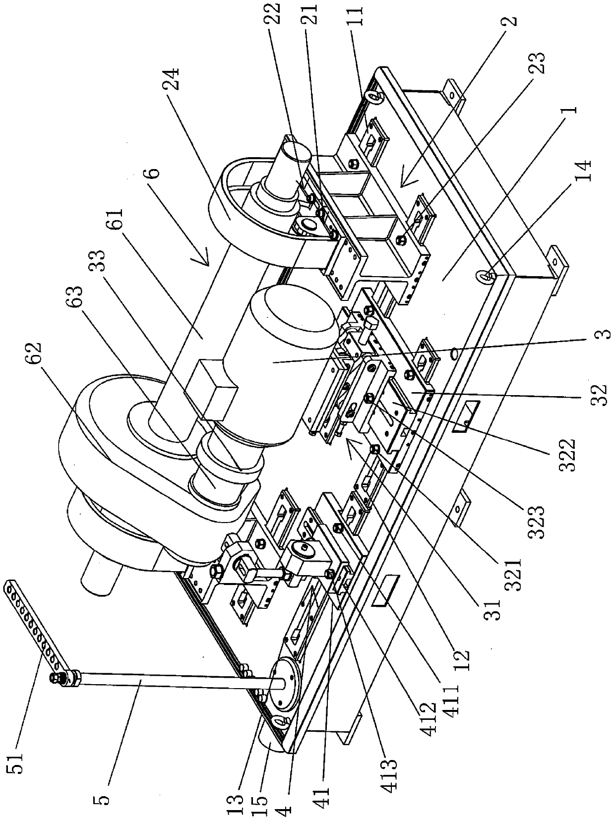
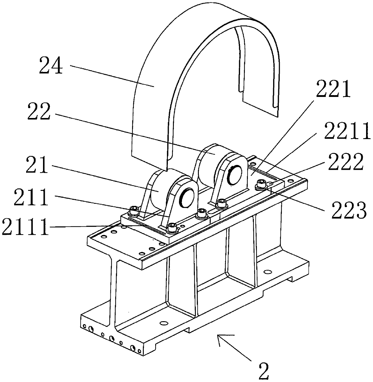
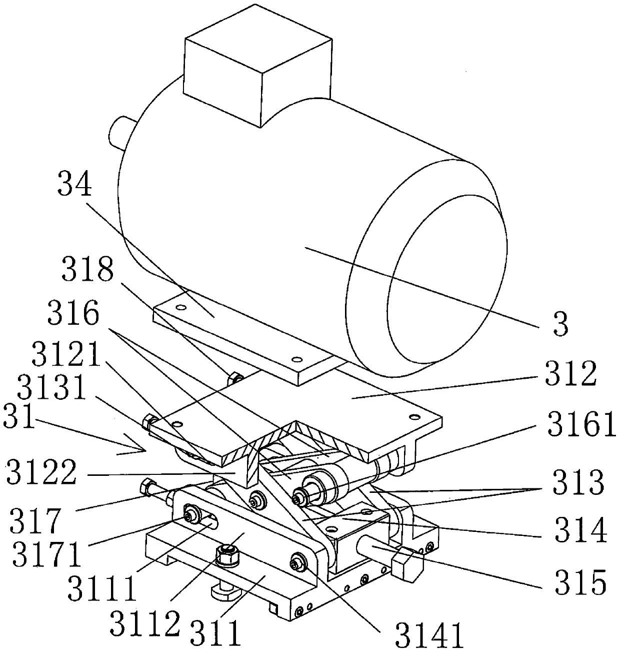
[0026] see figure 1 and combine figure 2 , image 3 , Figure 4 and Figure 5 , the present invention relates to a run-in test device for a shaft gearbox of a rail train, comprising a base 1, a pair of support bases 2 installed above the base 1 and symmetrically arranged ...


PUM


Abstract

The invention discloses a running-in testing device of a rail train gear box with a shaft, and belongs to the technical of the rail traffic. The testing device comprises a base, a pair of supporting seats arranged on the base and symmetrically arranged at left and right, a motor and a gear box fixing device arranged on the base; the supporting seats slide on the base along a left-right direction,the motor is arranged on a lifting device, the lifting device is arranged on the base along a left-right direction and a forward-backward direction in the sliding manner; the gear box fixing device isarranged along the left-right direction and the forward-backward direction in the sliding manner; a fixed pulley and a movable pulley are arranged on the supporting seats; and the movable pulley is arranged along the forward and backward direction in the sliding manner. The dismounting difficulty of the gear box with the shaft is reduced, the damage on the axle is avoided, and the detection efficiency is improved; and the testing device can be adapted to the running-in testing of the gear box with the shaft in different specifications and different transmission ratios; the use range is enlarged; a running-in testing platform is stable and reliable in running, the vibration amplitude is small, and the precision is high; the traveling unloading operation can be accomplished through one people, the operation is convenient, fast and labor-saving, and the service life is long.

Description

technical field [0001] The invention belongs to the technical field of rail transportation, and in particular relates to a run-in test device for a gear box with a shaft of a rail train. Background technique [0002] With the development of society, rail trains are gradually popularized in people's lives. Rail lines spread all over the city. Gearboxes with shafts are one of the important components of rail trains. The quality of gearboxes with shafts directly affects the track The operation of the train is safe, so testing whether the assembly quality of the gearbox with shaft is qualified is the most important link in the production (maintenance) process of the gearbox with shaft. , Unreasonable temperature changes. The industry generally uses running-in platforms for testing. Currently, the running-in platforms on the market are mainly divided into the following types: 1. Thimble-type running-in test platform, which uses thimbles to tighten the two ends of the shaft for r...

Claims


Application Information

Patent Timeline
Patent Type & Authority Applications(China)
IPC IPC(8): G01M13/021G01M13/025
CPCG01M13/021G01M13/025
Inventor 顾亚君许洪洋
Owner 中路轨道设备(常熟)有限公司
Why Eureka
Try Eureka